Curved-surface machining cutter track planning method using cutting force fluctuation as constraint

A surface processing and tool trajectory technology, applied in the direction of electrical program control, digital control, etc., can solve the problems of not considering the influence of processing quality, not considering the influence of surface processing quality, and inappropriateness, and achieve the optimal tool line spacing and step long effect

Active Publication Date: 2016-11-16
DALIAN UNIV OF TECH
View PDF7 Cites 20 Cited by
  • Summary
  • Abstract
  • Description
  • Claims
  • Application Information

AI Technical Summary

Problems solved by technology

The document "Tool path generation for freeform surface models" by Elber et al., Computer-Aided Design, 2004, 26(6), 490-496, aimed at the shortcomings of redundant and over-dense tool paths generated by the isoparametric line method, Invented the self-adaptive optimization isoparametric line method, the length of the generated tool path is shorter, and the processing efficiency is improved. However, the isoparametric line method is not suitable for generating the tool path of the compo

Method used


Image

  • Curved-surface machining cutter track planning method using cutting force fluctuation as constraint
  • Curved-surface machining cutter track planning method using cutting force fluctuation as constraint
  • Curved-surface machining cutter track planning method using cutting force fluctuation as constraint

Examples


Embodiment Construction

[0046] The specific implementation manner of the present invention will be described in detail in conjunction with the technical scheme and the accompanying drawings.

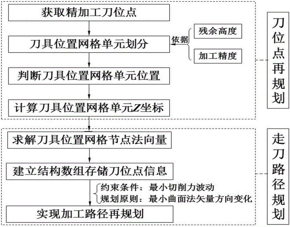
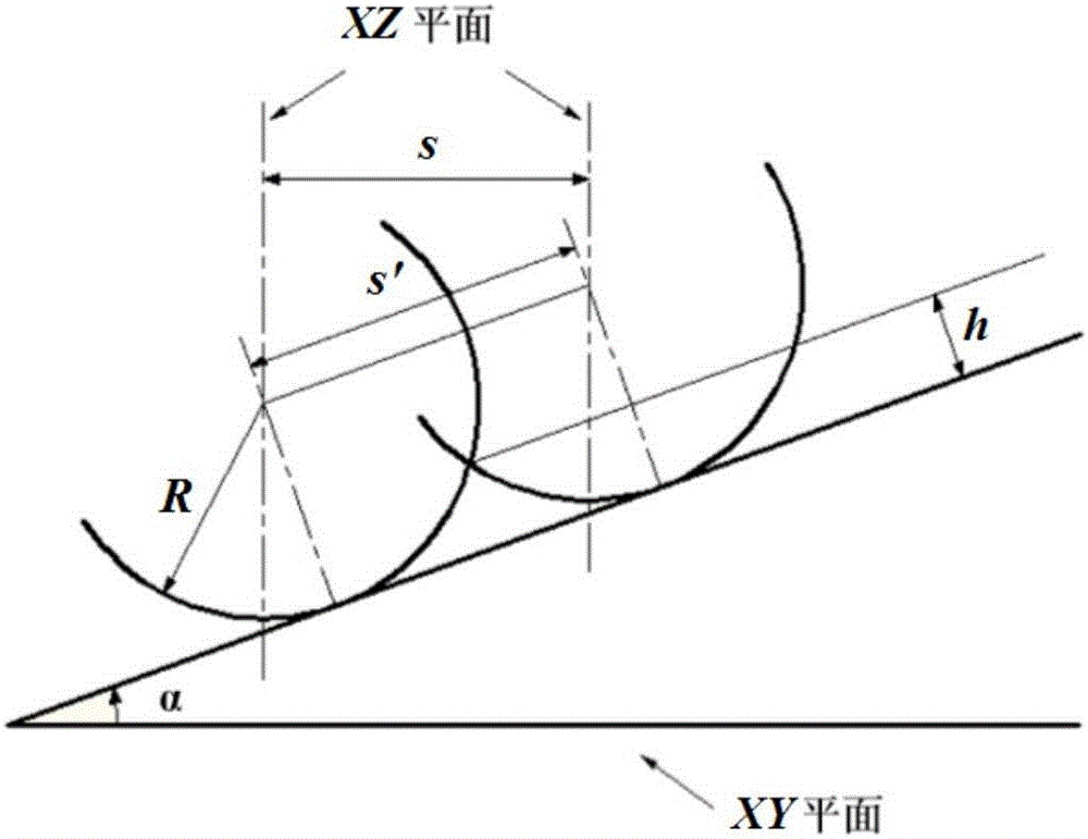
[0047] figure 1 is the overall flowchart of the method, figure 2 Shown is the calculation method of the line spacing of the ball end milling cutter on the inclined plane.

[0048] In view of the fact that the geometric characteristics of each point on the surface are often inconsistent, the milling force fluctuates violently during the CNC machining process, which affects the machining quality. Based on this, aiming at the problem that the cutting force fluctuation affects the machining quality of curved surface in the machining process, a tool path planning method for curved surface machining with cutting force fluctuation constraint was invented.

[0049] Taking the three-axis end milling saddle surface of a ball end mill as an example, the implementation process of the present invention is described in d...


PUM


Abstract

The invention relates to a curved-surface machining cutter track planning method using cutting force fluctuation as a constraint, which belongs to the technical field of the high-efficiency milling processing for complicated curved-surface parts. According to the method, on the basis of cutter location point data obtained by an equal-residual-height method, an optimal feeding ling spacing value and an optimal feeding step length are determined, thereby realizing a cutter location grid unit division based on a cutter location grid node. With fitting of a cutter location grid unit plane, a cutter location grid node Z coordinate is determined by combining an adjacent associated cutter location grid unit. And then a cutter location grid node normal vector is calculated; and with the cutting force fluctuation during the processing process as a constraint, a curved-surface processing cutter track is planned by using the cutter location grid node as a cutter location point according to a fundamental principle of normal vector included angle minimization between adjacent cutter location points, so that the high-quality and high-efficiency curved surface processing is realized. The method has the high adaptability to the local complicated geometrical features; and high-quality and high-efficiency curved surface processing is realized.

Description

technical field [0001] The invention belongs to the technical field of high-efficiency milling processing of complex curved surface parts, and in particular relates to a tool path planning method for curved surface processing constrained by cutting force fluctuations. Background technique [0002] Complex surface parts are widely used in aerospace, automobile, ship and mold and other fields. Nowadays, the complex surface modeling technology is relatively mature, but its high-quality and efficient processing is still a hot and difficult point in the industrial field. The multi-axis linkage CNC machine tool provides a reliable way for the processing of complex curved surfaces, and also greatly improves its processing quality and processing efficiency. In the process of NC machining, the tool path planning is closely related to the machining accuracy and efficiency of the parts, and also directly affects the tool life and the dynamic characteristics of the machine tool. Reaso...

Claims


Application Information

Patent Timeline
IPC IPC(8): G05B19/19
CPCG05B19/19
Inventor 马建伟高媛媛贾振元宋得宁刘振张鑫
Owner DALIAN UNIV OF TECH
Why Eureka
Try Eureka