
Rotor homopolarity magnetic steel bonding and positioning device

A positioning device and a technology of the same polarity, which is applied in the direction of electromechanical devices, manufacture of stator/rotor body, manufacture of motor generators, etc., can solve problems such as the inability to achieve magnetic steel bonding on the outer surface of the rotor, and achieve improved assembly speed and assembly High precision, improved processing efficiency, and simple structure

Active Publication Date: 2016-11-16
GUIZHOU AEROSPACE LINQUAN MOTOR CO LTD
View PDF7 Cites 6 Cited by
  • Summary
  • Abstract
  • Description
  • Claims
  • Application Information

AI Technical Summary

Problems solved by technology

However, it is only suitable for bonding the magnetic steel on the surface of the circular inner hole, and cannot realize the bonding of the magnetic steel on the outer surface of the rotor.
[0006] To sum up, most of the existing magnetic steel bonding devices are only suitable for the magnetic steel bonding of the servo motor stator or the magnetic steel bonding of the non-magnetic substrate. Bonding of round surface magnetic steel

Method used


Image

  • Rotor homopolarity magnetic steel bonding and positioning device
  • Rotor homopolarity magnetic steel bonding and positioning device
  • Rotor homopolarity magnetic steel bonding and positioning device

Examples


Embodiment Construction

[0031] The technical solution of the present invention is further described below in conjunction with the accompanying drawings of the embodiments, but the scope of protection is not limited to the description.

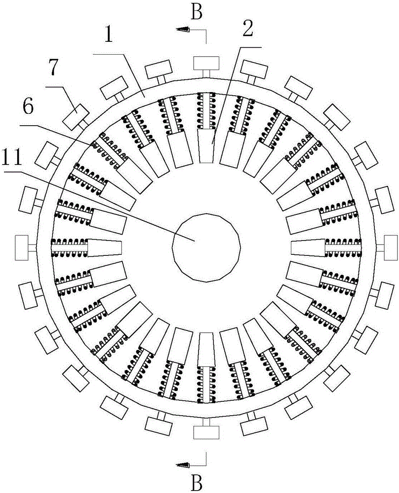
[0032] Such as image 3 , Figure 4 As shown, a magnetic steel bonding positioning device with the same polarity of the rotor includes a positioning sleeve 1 and a number of elastic components uniformly arranged along the circumferential direction of the positioning sleeve 1. The elastic components are composed of screws 7, tightening blocks 2 and springs 6 , the fastening block 2 is located inside the positioning sleeve 1 and connected to the end of the screw 7, the spring 6 is set on the screw 7, and is located between the fastening block 2 and the positioning sleeve 1, and the center of the positioning sleeve 1 A positioning boss 11 is also provided. Using this positioning device, when bonding the rotor magnetic steel, if Figure 9 , Figure 10 As shown, put th...


PUM


Abstract

The invention discloses a rotor homopolarity magnetic steel bonding and positioning device. The device comprises a positioning sleeve and a plurality of elastic assemblies, wherein the plurality of elastic assemblies are uniformly arranged along a circumferential direction of the positioning sleeve, each elastic assembly comprises a screw, a tightening block and a spring, the tightening block is arranged at an inner side of the positioning sleeve and is connected with an end part of the screw, the spring sleeves the screw and is arranged between the tightening block and the positioning sleeve, a positioning boss is further arranged at the center of the positioning sleeve, the screw comprises a screw rod and a screw head, the screw rod and the screw head are connected by a square boss, a screw insertion hole is formed in the positioning sleeve and is used for installing the screw, and a square groove is formed above the screw insertion hole and is matched with the square boss. By the device, adjacent magnetic steels repellent to each other can be rapidly and reliably bonded, and the assembly speed and the assembly accuracy are obviously improved. The device is simple in structure, is easy to manufacture and rapid to operate, and can be widely promoted and applied in the technical field of rotor magnetic steel bonding.

Description

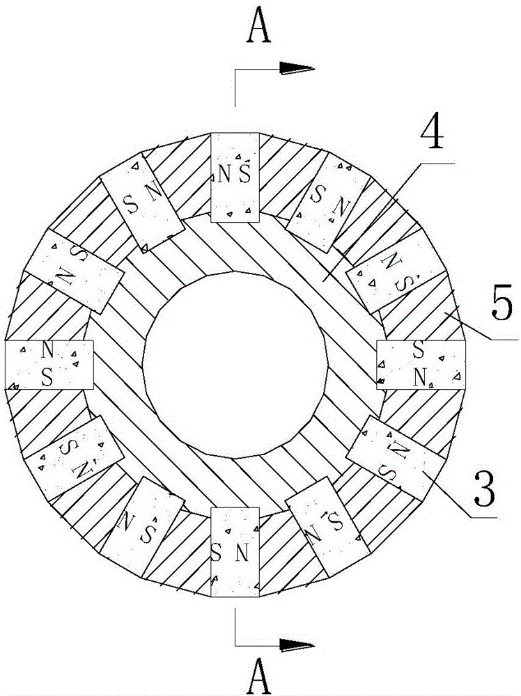
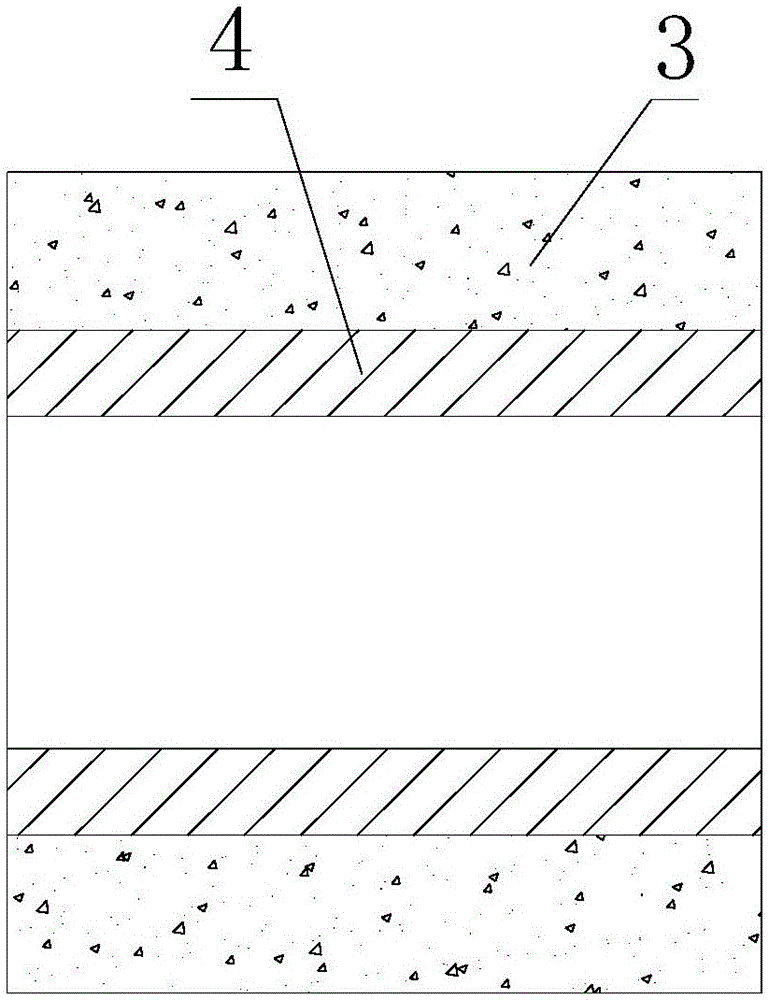
technical field [0001] The invention relates to a rotor magnetic steel bonding and positioning device, in particular to a rotor magnetic steel bonding and positioning device with the same polarity. Background technique [0002] Such as figure 1 , figure 2 As shown, the high-power alternator rotor is generally composed of a shaft 4, a yoke 5, and a magnetic steel 3. The yoke 5 and the magnetic steel 3 are fixed on the shaft 4 by adhesive bonding. Since the polarity of the adjacent magnetic steel 3 Mutual repulsion. Before the adhesive is cured, its repulsive force is greater than the adhesive force. During assembly, pressure must be applied to fix the magnetic steel 3 on the shaft 4 until the adhesive is cured. In order to realize the bonding of magnetic steel and ensure the bonding quality and bonding efficiency, various bonding positioning devices have appeared at present. [0003] For example, the Chinese patent with the publication number CN204089524U discloses a stat...

Claims


Application Information

Patent Timeline
Patent Type & Authority Applications(China)
IPC IPC(8): H02K15/03
CPCH02K15/03
Inventor 田胤蓬焦保坤虞静
Owner GUIZHOU AEROSPACE LINQUAN MOTOR CO LTD
Learn More