A Method of Inverting es Layer Parameters Based on Backscattered Ionogram

A backscattering and ionogram technology, applied in the field of ionospheric physics research, can solve problems such as inability to meet the actual situation, and achieve the effect of meeting engineering needs

Inactive Publication Date: 2014-02-19
THE 22ND RES INST OF CHINA ELECTRONICS TECH GROUP CORP
View PDF0 Cites 8 Cited by
  • Summary
  • Abstract
  • Description
  • Claims
  • Application Information

AI Technical Summary

Problems solved by technology

Based on this Es model, assuming that Es is a complete mirror, the critical frequency and maximum electron concentration height of the Es layer are deduced, but this deduction method contains too many assumptions, such as the height and half-thickness of Es need to be assumed in advance, etc. parameters, in many cases cannot meet the actual situation

Method used


Image

  • A Method of Inverting es Layer Parameters Based on Backscattered Ionogram
  • A Method of Inverting es Layer Parameters Based on Backscattered Ionogram
  • A Method of Inverting es Layer Parameters Based on Backscattered Ionogram

Examples


example 1

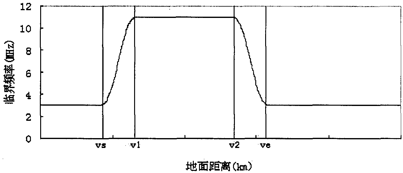
[0062] Suppose the Es layer parameters are as follows: r m E. s = 90km, y m E. s = 0.8km, f c E. s = 4.5MHz. This is an Es layer with a medium electron concentration.

[0063] 1) There is an Es layer along the entire backscatter detection path

[0064] The Es layer exists along the entire backscatter detection path, which rarely occurs in practice, but to illustrate the problem, first consider the synthetic backscatter ionogram in this case. Assuming that the lowest elevation angle of the antenna is 0°, without considering the second hop, the farthest distance of backscatter detection is determined by the 0-degree ray. At this time, the synthesized backscatter ionization map is shown in the attached figure 2 shown. This situation is easy to understand, and the leading edge of the backscatter ionogram depends entirely on the QPS model parameters.

[0065] 2) The Es layer exists in an area about 413km away from the transmitter

[0066] In this case, the synthesized b...

example 2

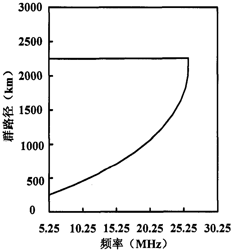
[0070] Suppose the Es layer parameters are as follows: r m E. s = 100km, y m E. s = 1.0km, f c E. s =7.7MHz. This is an Es layer with a higher electron concentration.

[0071] 1) There is an Es layer along the entire backscatter detection path

[0072] The farthest distance of backscatter detection is determined by the 0-degree ray, since the critical frequency of Es is f c E. s = 7.7MHz, so frequencies lower than 7.7MHz are equivalent to vertical detection, so a fairly flat front is formed, and frequencies above 7.7MHz form a front determined by the QPS parameter. At this time, the edge profile of the synthesized backscatter ionogram as attached Figure 5 shown. Since the highest frequency of backscatter detection is generally up to 30MHz, the backscatter ionogram synthesized here only shows up to 30MHz.

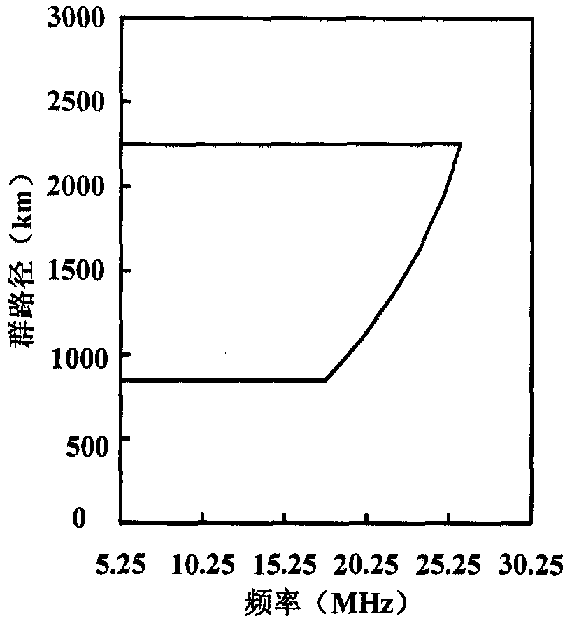
[0073] 2) The Es layer exists in an area about 254km away from the transmitter

[0074] In this case, it can be seen that the ground distance of 254 km correspo...


PUM


Abstract

The present invention provides a method for inverting Es layer parameters based on backscattered ionograms, which includes the following steps: Step A: using the established Es layer model to invert the Es layer parameters according to the measured backscattered ionograms' steep front information QPS parameters include the critical frequency, peak height, and half-thickness of Es; Step B: Calculate the elevation angle corresponding to the flat leading and trailing edges of the backscatter ionogram according to the determined QPS parameters to determine the area where Es exists. The present invention uses the inferred Es parameters to synthesize the front and rear edges of the backscattered ionization map Es, which can well conform to the measured Es front and back edges, and can better obtain the vertical distribution and horizontal distribution of the electron concentration in the ES layer, overcoming the traditional definition that considers the electron concentration alone The lack of vertical distribution or spatial distribution of electron concentration can better meet engineering needs.

Description

technical field [0001] The invention relates to the field of ionospheric physics research, in particular to a method for retrieving Es layer parameters based on backscattered ionograms. Background technique [0002] Whether it is high-frequency short-wave communication or sky-wave over-the-horizon radar system, the ionosphere is used as the medium for signal transmission, and the ionosphere is a special medium with time-varying dispersion, which makes these systems unable to select operating frequencies and Perform parametric design. In order to ensure the normal operation of high-frequency communication and other systems that use the ionosphere as the transmission medium, it is necessary to have a real-time understanding of the state of the ionosphere and predict the short-term state. [0003] The Es layer is a sudden inhomogeneous structure in the E region. Its thickness is generally 100m-2km, its horizontal scale is 200m-1000km, and it is generally located in the area of...

Claims


Application Information

Patent Timeline
Patent Type & Authority Patents(China)
IPC IPC(8): G06F19/00
Inventor 王世凯郭延波
Owner THE 22ND RES INST OF CHINA ELECTRONICS TECH GROUP CORP
Why Eureka
Try Eureka