Cooking appliance and electric heating device for same

A technology for electric heating devices and cooking utensils, which is applied in the direction of induction heating devices, heating devices, electric heating fuel, etc., which can solve the problems of small resonant coil current, long IGBT tube conduction time, and failure to satisfy users, and achieve IGBT tube Less loss, better cooking effect, and better user satisfaction

Active Publication Date: 2016-11-23
FOSHAN SHUNDE MIDEA ELECTRICAL HEATING APPLIANCES MFG CO LTD +1
View PDF14 Cites 7 Cited by
  • Summary
  • Abstract
  • Description
  • Claims
  • Application Information

AI Technical Summary

Problems solved by technology

[0003] Therefore, when the heating power is large, the conduction time of the IGBT tube is long, the current of the resonant coil is large, and its inertia energy is also large, which is enough to make the voltage of the C pole drop to 0 volts, and the IGBT tube is in a soft switching state when it is turned on again , the IGBT tube loss is small; however, when the heating power is small, due to the short conduction time of the IGBT tube, the energy absorbed by the resonant coil is small, the current of the resonant coil is small, and its inertial energy is also small, so that the voltage of the C pole cannot be reduced to 0 volts, the IGBT tube is in a hard switching state when it is turned on again, and the loss of the IGBT tube increases
The disadvantage of this related technology is that the electromagnetic heating device can only continuously heat in a narrow power range, such as 1000W-2000W. When the heating power is lower than 1000W, continuous heating cannot be realized due to the large loss and temperature rise of the IGBT tube. Low-power heating can only be realized by means of intermittent heating, but the cooking effect of intermittent intermittent heating is poor and cannot meet the needs of users

Method used


Image

  • Cooking appliance and electric heating device for same
  • Cooking appliance and electric heating device for same
  • Cooking appliance and electric heating device for same

Examples


Embodiment Construction

[0022] Embodiments of the present invention are described in detail below, examples of which are shown in the drawings, wherein the same or similar reference numerals designate the same or similar elements or elements having the same or similar functions throughout. The embodiments described below by referring to the figures are exemplary and are intended to explain the present invention and should not be construed as limiting the present invention.

[0023] A cooking appliance for an air conditioner and an electric heating device for the cooking appliance according to embodiments of the present invention will be described below with reference to the accompanying drawings.

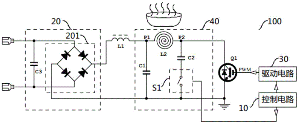
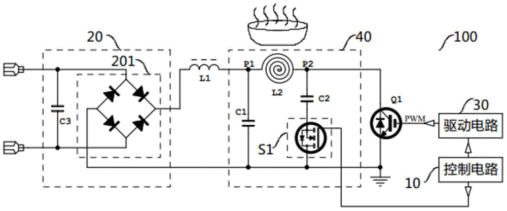
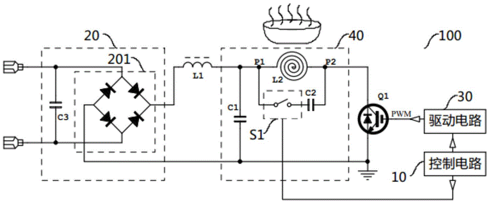
[0024] Such as Figure 1-Figure 4 As shown, the electric heating device 100 for cooking utensils according to the embodiment of the present invention includes: a first inductor L1, an IGBT (Insulated Gate Bipolar Transistor, insulated gate bipolar transistor) tube Q1, a resonant unit 40, a switch assembly ...


PUM


Abstract

The invention discloses a cooking appliance and an electric heating device for the cooking appliance. The electric heating device comprises a first inductor, an IGBT, a resonance unit and a control circuit. The first end of the first inductor is connected with a power source, the first end of the IGBT is grounded, the resonance unit comprises a resonance coil, a first capacitor, a second capacitor and a switching assembly, the control circuit is connected with the IGBT and the switching assembly, the control circuit is used for generating PWM waves, controlling the IGBT according to the PWM waves, and controlling the switching assembly to be turned on while controlling the IGBT to be turned off and controlling the switching assembly to be turned off while controlling the IGBT to be turned on when low-power heating is carried out, the power range of continuous heating is enlarged, and user cooking experience is improved.

Description

technical field [0001] The invention relates to the technical field of living appliances, in particular to a cooking appliance and an electric heating device for the cooking appliance. Background technique [0002] The output power of the relevant electromagnetic heating device is usually relatively large, generally as high as more than 2,000 watts. In the related art, the electromagnetic heating device generally uses an LC resonant circuit for heating, so as to reduce the loss of the IGBT tube. For the LC resonant circuit, the voltage of the C pole (collector) of the IGBT tube is the superposition of the resonant voltage and the rectified mains voltage. When the IGBT tube is turned on, the resonant coil absorbs energy; when the IGBT tube is turned off, in addition to most of the energy being transmitted to the pot, there is also a part of inertial energy that reverse charges the resonant capacitor, causing the voltage of the C pole of the IGBT tube to drop. [0003] There...

Claims


Application Information

Patent Timeline
Patent Type & Authority Applications(China)
IPC IPC(8): A47J27/00A47J36/24H05B6/12H05B6/06F24C7/00
CPCY02B40/00
Inventor 曾露添李宝刚江德勇
Owner FOSHAN SHUNDE MIDEA ELECTRICAL HEATING APPLIANCES MFG CO LTD
Why Eureka
Try Eureka