Coating machine with replaceable drum
A coating machine and drum-type technology, which is applied in the direction of making medicines into special physical or taking forms, cleaning methods using liquids, coatings, etc., can solve the problems of not being able to adapt to the production of material volume or weight, and achieve The cleaning time is short, the cleaning effect is good, and the effect of avoiding cross contamination
- Summary
- Abstract
- Description
- Claims
- Application Information
AI Technical Summary
Problems solved by technology
Method used
Image

Examples
specific Embodiment approach 1
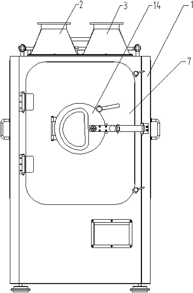
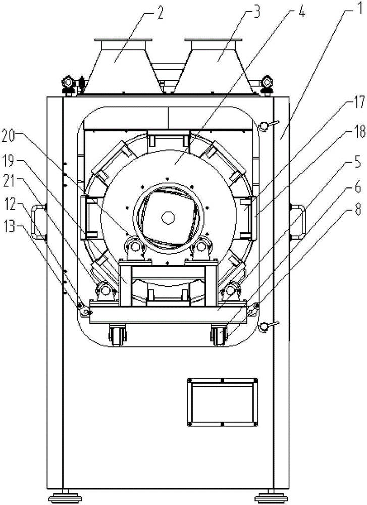
[0041] Specific implementation mode one: combine Figure 1 to Figure 12 Describe this embodiment, a replaceable drum coating machine of this embodiment includes a body 1 and an air duct system, the air duct system is installed in the body 1, and the inlet and outlet ends of the air duct system are all upward, it also includes a transmission Shaft 10, bushing 11, baffle plate 12, first guide rail 8 and roller units with different volumes. Two parallel first guide rails 8 are arranged inside the body 1 along the front and rear directions. The roller unit is detachably installed in the body 1. And the roller unit is slidably installed on the first guide rail 8, the roller unit includes a roller 4 and a roller support car 5, the roller 4 is detachably and rotatably mounted on the roller support car 5, and the bottom four corners of the roller support car 5 are respectively provided with There are a plurality of guide wheels 6 that can rotate along the axial direction of the drum. ...
specific Embodiment approach 2
[0051] Specific implementation mode two: combination Figure 5 to Figure 7 To illustrate this embodiment, the distance between the axes of the two first runners 20 of this embodiment is smaller than the diameter of the mouth wall 22 of the drum 4, and the rear end of the drum support vehicle 5 is equipped with two axes along the front and rear direction, the distance between the axes of the two second runners 21 is smaller than the diameter of the movable wind plate 15, and the second runner 21 is a concave wheel, and the concave wheel on its wheel surface The width of the groove matches the thickness of the movable wind-passing plate 15 . It is convenient to realize the cooperation between the drum 4 and the drum supporting vehicle 5 . Other compositions and connections are the same as in the first embodiment.
specific Embodiment approach 3
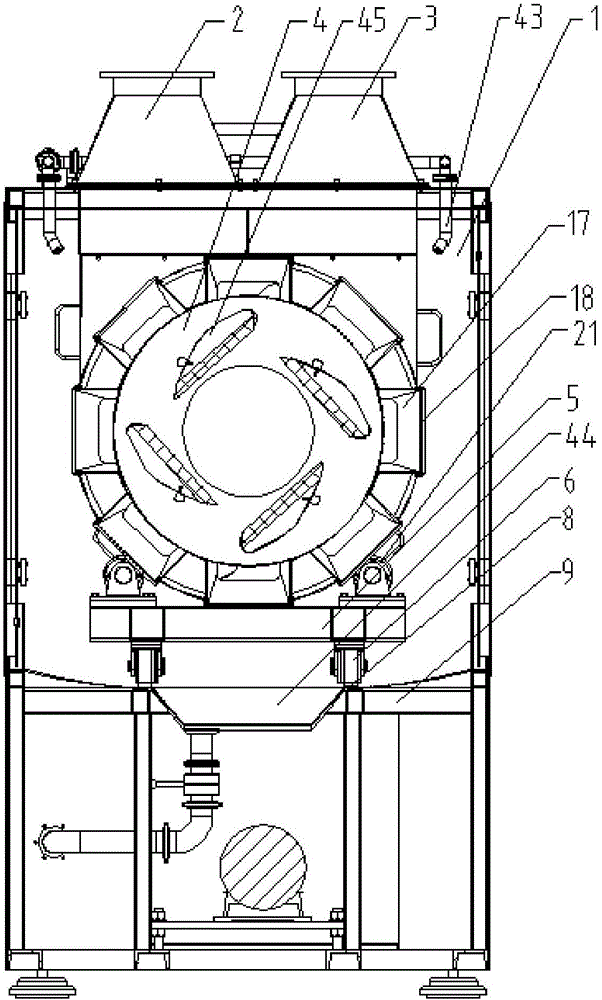
[0052] Specific implementation mode three: combination Figure 1 to Figure 4 , Figure 9 to Figure 12 Describe this embodiment, the air duct system of this embodiment includes air inlet pipe 2, air outlet pipe 3, fixed air passing plate 34 and connecting tube 38, the middle part of air inlet pipe 2 is provided with air inlet 36, and the middle part of air outlet pipe 3 The lower part is provided with an air outlet 37, the lower part of the air inlet pipe 2 and the air outlet pipe 3 are connected, and two arc-shaped ventilation holes 35 are opened on the fixed wind board 34, and the fixed wind board 34 is installed on the air inlet through the connecting cylinder 38. The intersection of the pipe 2 and the air outlet pipe 3, and adjust the coincidence degree of the ventilation hole 35 with the air inlet 36 and the air outlet 37 by adjusting the position of the fixed air passage plate 34 on the connecting cylinder 38. It is convenient to adjust the air volume, and the other comp...
PUM
 Abstract
Description
Claims
Application Information
 - R&D
- Intellectual Property
- Life Sciences
- Materials
- Tech Scout
- Unparalleled Data Quality
- Higher Quality Content
- 60% Fewer Hallucinations
Browse by: Latest US Patents, China's latest patents, Technical Efficacy Thesaurus, Application Domain, Technology Topic, Popular Technical Reports.
© 2025 PatSnap. All rights reserved.Legal|Privacy policy|Modern Slavery Act Transparency Statement|Sitemap|About US| Contact US: help@patsnap.com