Carbon dioxide arc welding device provided with safety goggles
A gas shielded welding and carbon dioxide technology, which is used in welding equipment, welding accessories, arc welding equipment, etc., can solve the problems of poor welding quality, unsatisfactory welding shape cleanliness, and high labor intensity of workers. The effect of swinging the gun head and reducing labor intensity
- Summary
- Abstract
- Description
- Claims
- Application Information
AI Technical Summary
Problems solved by technology
Method used
Image

Examples
Embodiment Construction
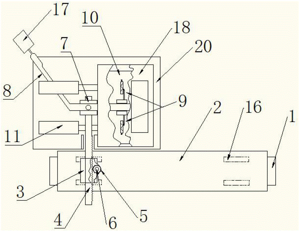
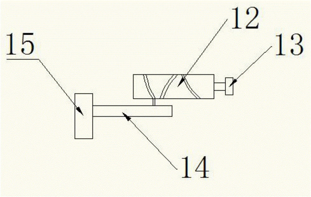
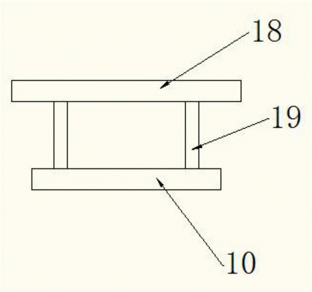
[0014] Example. A carbon dioxide gas shielded welding device with protective glasses, constituted as Figure 1-3 As shown, including track 1, track 1 is provided with trolley 2, and trolley 2 is connected with transparent box 20; Cart 2 is also provided with fixed block 3, and fixed block 3 is provided with gear 5, and gear 5 is connected with motor 6; The rack 4 meshing with the gear 5 is connected with a transverse limit block 7, the transverse limit block 7 is connected with the gun head 8 through bolts, the gun head 8 is connected with a welding machine 17, and the two sides of the end of the gun head 8 are provided with a fine-tuning mechanism 9. The fine-tuning mechanism 9 is arranged on the moving plate 10, and the moving plate 10 is connected with the protective mirror 18 through the support rod 19; the moving plate 10 is also connected with the cylinder 11; the fine-tuning mechanism 9 includes a rotation button 13, and the rotation button 13 is connected with The wor...
PUM
 Abstract
Description
Claims
Application Information