Bevel gear speed reducer

A technology of bevel gear reducer and large gear, applied in the direction of gear transmission, belt/chain/gear, transmission parts, etc., can solve the problem of affecting transmission accuracy and service life, affecting use safety and service life, bevel gear pair collision problems, to achieve a good effect of transmitting torque, improve service life and work performance, and ensure the effect of accuracy

Inactive Publication Date: 2016-11-23
DIBAISHI MOTOR TECH SUZHOU CO LTD
View PDF5 Cites 1 Cited by
  • Summary
  • Abstract
  • Description
  • Claims
  • Application Information

AI Technical Summary

Problems solved by technology

However, the running stability of the bevel gear reducer currently used is poor, which affects the safety and life of use. At the same time, the gap between the bevel gear pair and the tooth surface will become larger after the tooth surface is worn, which will cause the bevel gear pair to collide and make noise during transmission. Seriously affect transmission accuracy and service life

Method used


Image

  • Bevel gear speed reducer
  • Bevel gear speed reducer

Examples


Embodiment Construction

[0016] The present invention will be further described below in conjunction with the accompanying drawings.

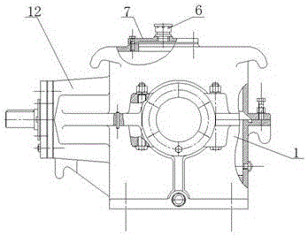
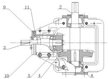
[0017] Such as figure 1 and figure 2 As shown, a bevel gear reducer includes a base 1, a first bearing 2, a second bearing 3, a bevel pinion 5, a bevel gear 4 and an aerator 6, and the base 1 is provided with a machine cover 12, and the base 1 is respectively provided with a first bearing 2 and a second bearing 3, the first bearing shaft 2 is connected to the conical bull gear 4, the second bearing 3 is connected to the conical pinion 5, and the conical bull gear 4 and the bevel pinion 5 are connected, The first bearing 2, the bevel gear 4, the second bearing 3 and the bevel pinion 5 cooperate with each other, and a ventilator 6 is provided on one side of the machine base 1, and a peep hole cover 7 is provided between the breather 6 and the machine base 1 .

[0018] In this embodiment, sealing covers 9 are provided at the connections between the first bearing 2 and...


PUM


Abstract

The invention provides a bevel gear speed reducer. The bevel gear speed reducer comprises a machine base, a first bearing, a second bearing, a circular cone small gear, a circular cone large gear and a breather. A machine cover is arranged outside the machine base. The first bearing and the second bearing are arranged on the machine base. The first bearing is connected with the circular cone large gear. The second bearing is connected with the circular cone small gear. The circular cone large gear and the circular cone small gear are connected. The first bearing and the circular cone large gear are matched with each other. The second bearing and the circular cone small gear are matched with each other. The breather is arranged on one side of the machine base. A peephole cover is arranged between the breather and the machine base. The bevel gear speed reducer is simple in combination, the return difference between the gears is reduced, noise is reduced, abrasion of the gears is reduced, and therefore the service life of the gears is prolonged, and precision is ensured; and meanwhile, the work stability is improved, a good torque transmitting effect is achieved, the service life of the speed reducer is effectively prolonged, and the work performance of the speed reducer is effectively improved.

Description

technical field [0001] The invention relates to the technical field of reducers, in particular to a bevel gear reducer. Background technique [0002] The reducer plays the role of matching the speed and transmitting torque between the prime mover and the working machine or the actuator. The reducer is a relatively precise machine. The purpose of using it is to reduce the speed and increase the torque. According to the number of transmission stages, it can be divided into single-stage and multi-stage reducers; according to the shape of the gear wheel, it can be divided into cylindrical gear reducers, bevel gear reducers and conical-cylindrical gear pulley reducers; according to the layout of the transmission, it can be divided into It is divided into expansion type, split flow type and coaxial shaft type reducer. The reducer is an independent component consisting of gear transmission, worm transmission, and gear-worm transmission enclosed in a rigid shell, and is often used ...

Claims


Application Information

Patent Timeline
IPC IPC(8): F16H1/14F16H57/021F16H57/029F16H57/028
CPCF16H1/145F16H57/021F16H57/028F16H57/029
Inventor 王凯
Owner DIBAISHI MOTOR TECH SUZHOU CO LTD
Why Eureka
Try Eureka