Polymeric strain sensor

A strain sensor and polymer technology, applied in the field of strain sensors, can solve the problems of short service life and unsatisfactory polymer strain gauges

Inactive Publication Date: 2008-06-11
ROYAL MELBOURNE INST OF TECH
View PDF4 Cites 13 Cited by
  • Summary
  • Abstract
  • Description
  • Claims
  • Application Information

AI Technical Summary

Problems solved by technology

Polymer strain gauges that rely on a change in the resistance of a conductive f

Method used


Image

  • Polymeric strain sensor
  • Polymeric strain sensor
  • Polymeric strain sensor

Examples


Embodiment Construction

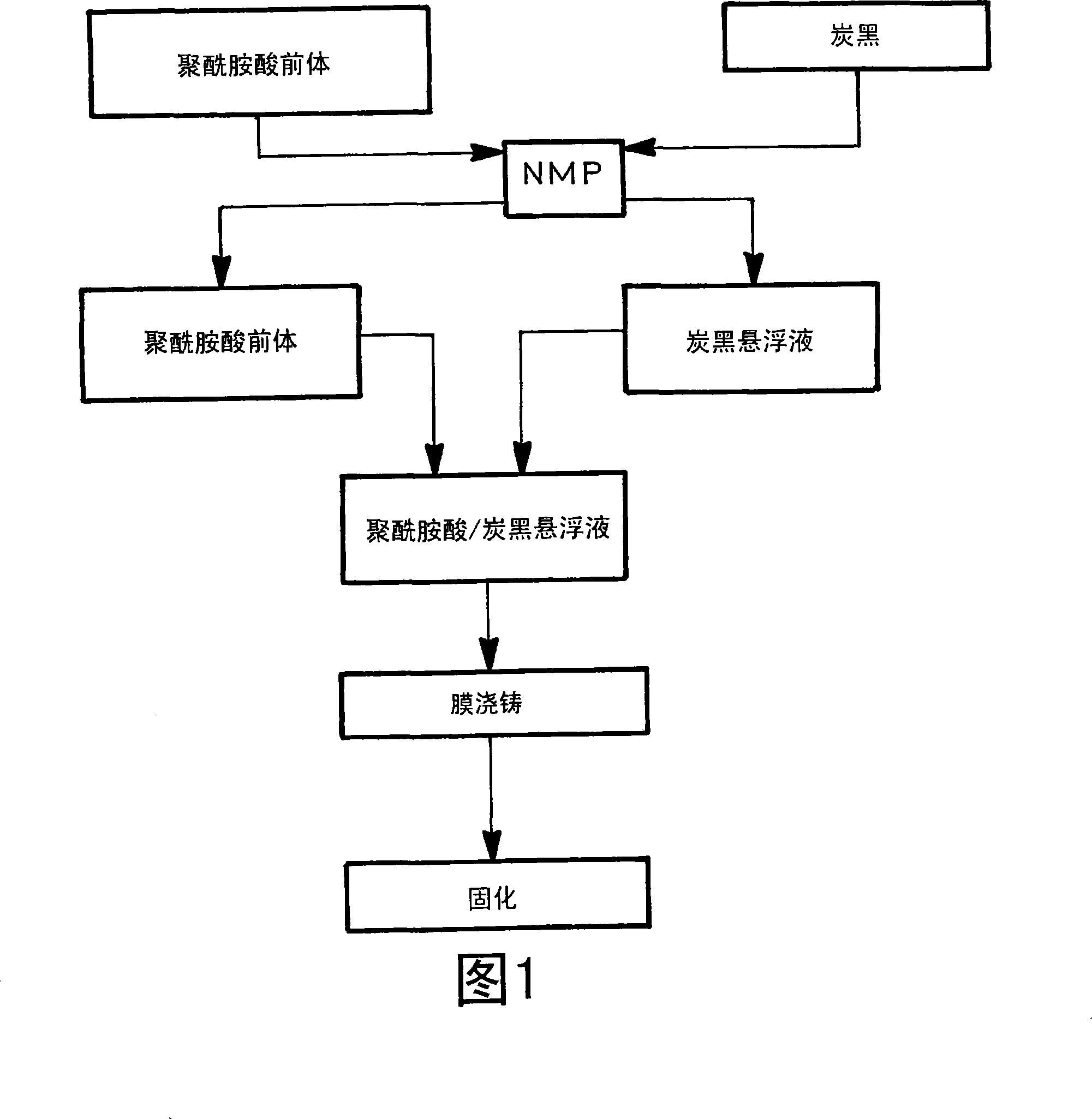
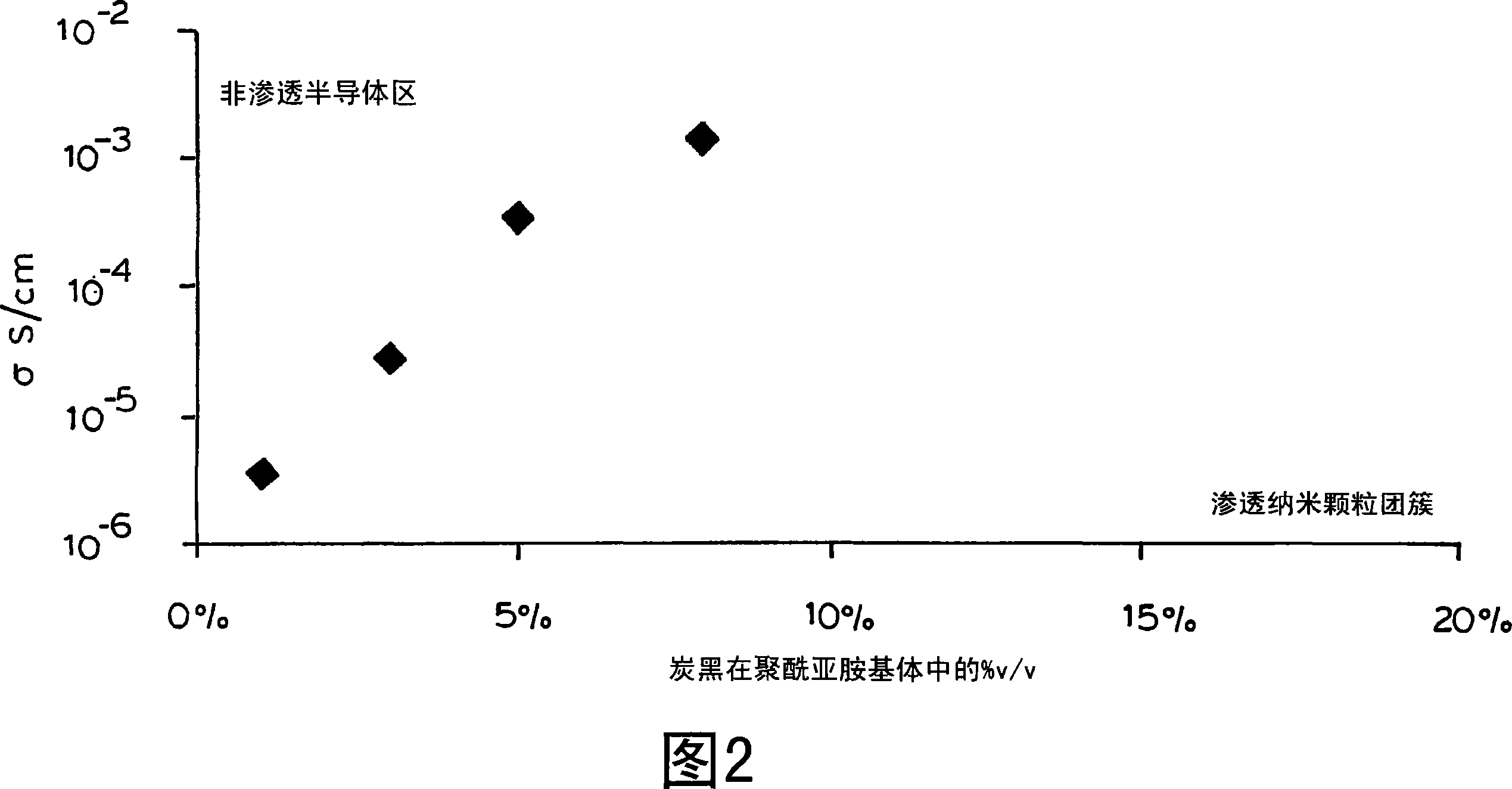
[0040] As shown in Figure 1, the nanocomposite film is prepared by mixing carbon black into the precursor of polyimide (i.e. polyamic acid of benzophenone tetracarboxylic dianhydride), and using n-methyl 2- Film formation of 4,4'-aminodiphenyl ether (BPDA-ODA) in pyrrolidone (NMP) solvent. The cast film is in the range of 50-100 microns. The carbon black has an average particle diameter of 30-70 nm and an aggregate particle size of 100-200 nm. The carbon loading is kept below 10% v / v, resulting in a conductivity of 10 -6 to 10 -2 Scm -1 and within the range of semiconductors, as shown in Figure 2.

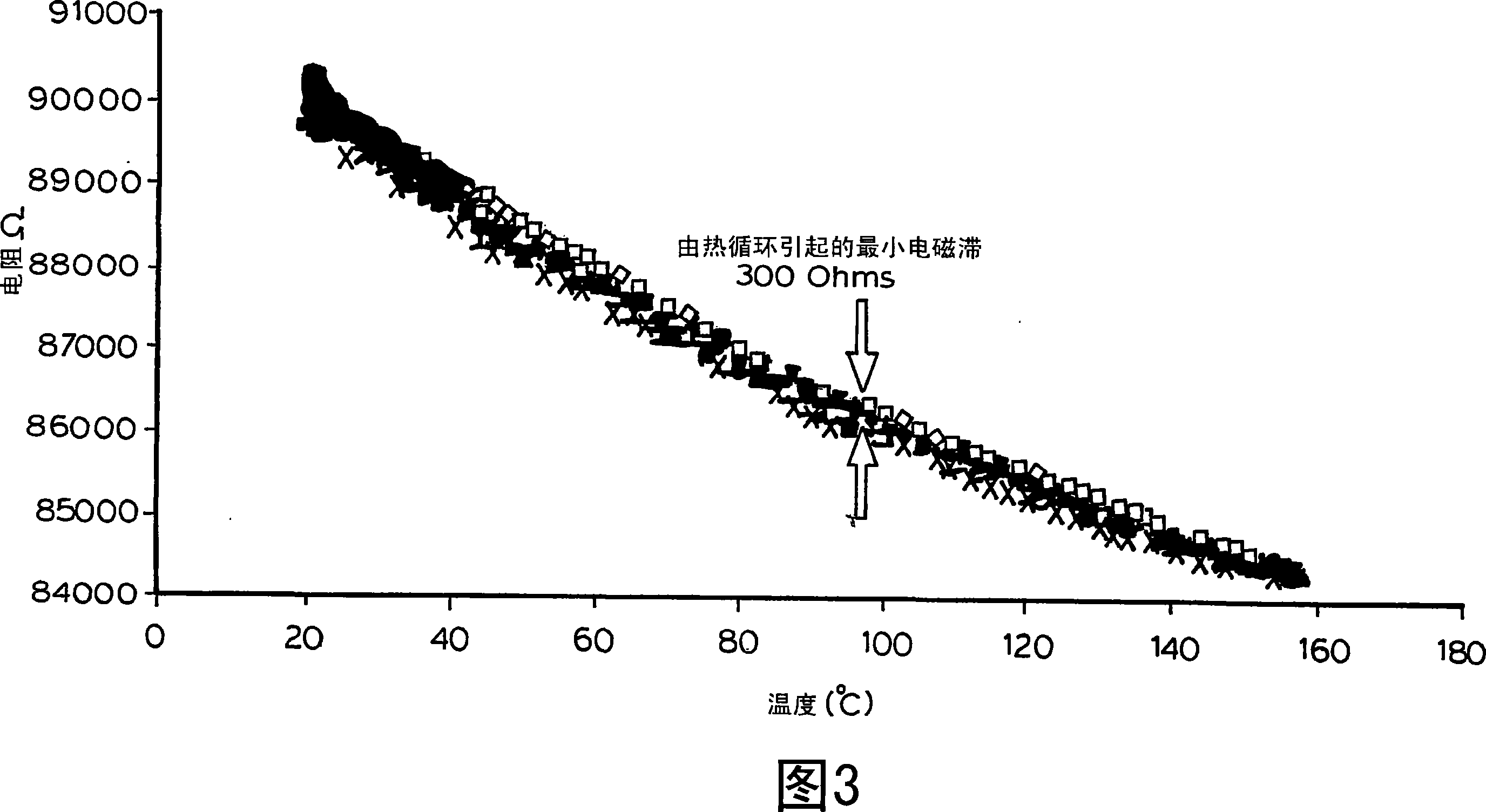
[0041] Figure 3 shows the resistance-temperature diagram of a nanocomposite film with a carbon content of 5% v / v cast on a silicon substrate. Resistance decreases with increasing temperature, which is typical for semiconductors. The figure also shows reduced resistive hysteresis behavior upon thermal cycling.

[0042] Figure 4 shows the temperature-dependent resistance chang...


PUM

PropertyMeasurementUnit
The average particle sizeaaaaaaaaaa
Conductivityaaaaaaaaaa

Abstract

A strain sensor consisting of a non-conductive polymer mixed with conductive nanoparticles below the percolation threshold and preferably less than 10% v/v of the polymer. The polymer is polyimide, and the conductive nanoparticles are carbon black with an average particle diameter of 30-40 nm and an aggregate particle size of 100-200 nm. The sensor can detect tension, compression and torsional strain.

Description

technical field [0001] The present invention relates to strain sensors, in particular micro-strain sensors, which are easy to manufacture and are used for continuous monitoring of structures under strained conditions. Background technique [0002] Polymer strain gauges have been proposed. [0003] US Patent 5,989,700 discloses the preparation of pressure sensitive inks that can be used in the manufacture of pressure sensors such as strain gauges, where the resistance is indicative of the applied pressure. The ink has an elastic polymer component, and semiconductor nanoparticles are uniformly dispersed in the polymer binder. [0004] US Patent 5,817,944 discloses a strain sensor for concrete structures containing electrically conductive fibers. [0005] US Patent 6079277 discloses a strain or stress sensor consisting of a polymer composite material and a carbon filament matrix. [0006] US Patent 6276214 discloses strain sensors using conductive particle-polymer complexes....

Claims


Application Information

Patent Timeline
IPC IPC(8): G01L1/22G01L1/20
Inventor D·梅因沃林P·莫加拉吉N·E·M·胡尔塔斯
Owner ROYAL MELBOURNE INST OF TECH
Why Eureka
Try Eureka