Magnetic element and magnetic element assembly method

A technology of magnetic components and assembly methods, applied in electrical components, magnetic cores/yokes, inductors with magnetic cores, etc., can solve the problems of increased device usage and increased board area of ​​power supplies, to simplify production and reduce losses , the effect of small size

Inactive Publication Date: 2018-02-23
HUAWEI TECH CO LTD
View PDF6 Cites 3 Cited by
  • Summary
  • Abstract
  • Description
  • Claims
  • Application Information

AI Technical Summary

Problems solved by technology

This kind of parallel interleaving power supply increases the usage of components, especially the core component of power conversion—inductance, which leads to a substantial increase in the footprint of the power supply on the circuit board.

Method used


Image

  • Magnetic element and magnetic element assembly method
  • Magnetic element and magnetic element assembly method
  • Magnetic element and magnetic element assembly method

Examples


Embodiment Construction

[0046] Embodiments of the present invention will be described below with reference to the drawings in the embodiments of the present invention.

[0047] The magnetic element provided by the invention is an integrated inductance element in a switching power supply, and can be applied to making an inductance element, a transformer, and the like. In the embodiments of the present invention, N-phase integrated inductors are formed by combining magnetic materials, N≥2, and the differences in permeability and reluctance of different magnetic materials are used to adjust the coupling coefficient between the inductance units of each phase, so as to realize magnetic circuit decoupling.

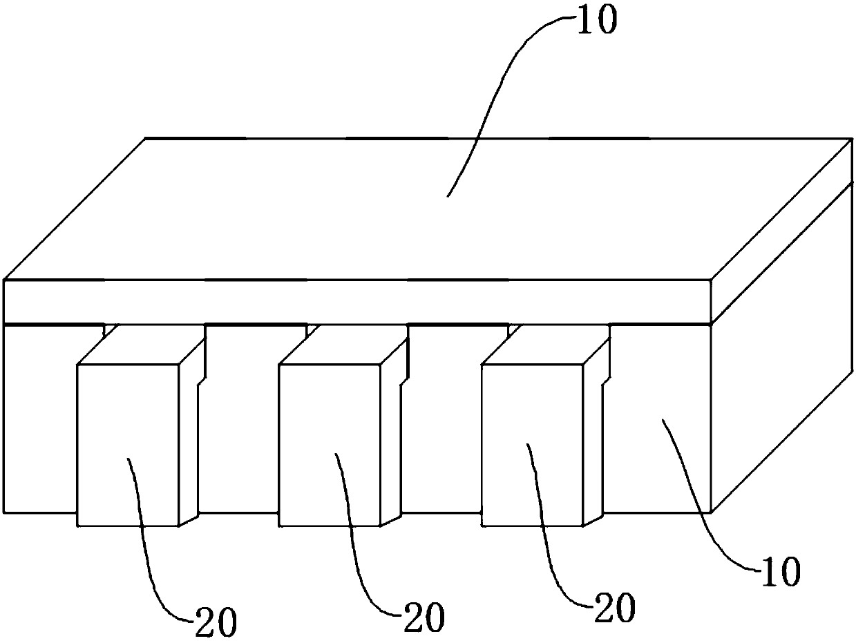
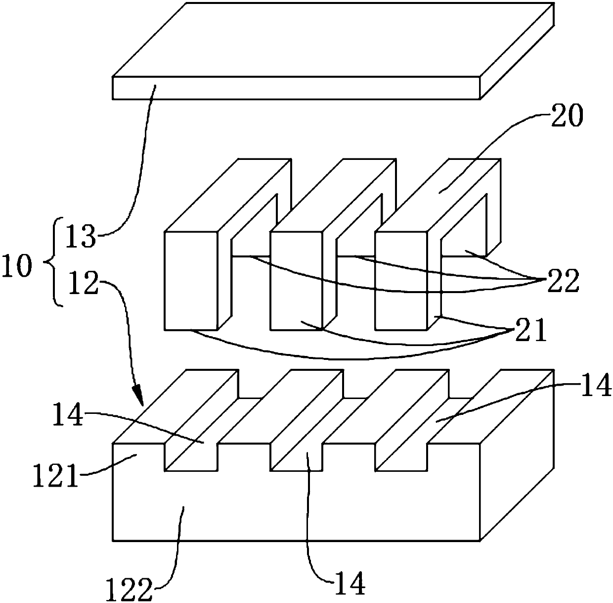
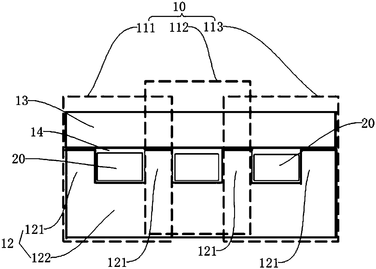
[0048] see figure 1 , figure 2 and image 3 , the magnetic element includes a magnetic core 10 and at least two electrodes 20 . The limitation of the number of at least two electrodes 20 does not mean that the electrodes 20 are independent of each other, and it may be that a plurality of electrodes...


PUM


Abstract

The embodiment of the invention discloses a magnetic element comprising a magnetic core and at least two electrodes. The magnetic element forms at least two phase inductive units. Adjacent inductive units share a part of the magnetic core. Each phase inductive unit includes a first magnetic core section and a second magnetic core section which are made of different materials, the first magnetic core section and the second magnetic core section are connected together to form a tubular framework with four closed sides and both opening ends, and the enclosed space in the tubular framework is an electrode slot; at least one of two electrodes is arranged in the electrode slot of each phase inductive element; the first magnetic core sections and the second magnetic core sections in all of the inductive units constitute the magnetic core together; the difference in the materials of the first magnetic core sections and the second magnetic core sections results in a difference in magnetic permeability between the first magnetic core sections and the second magnetic core sections. The invention also provides a magnetic element assembly method. The magnetic element enables the determination of coupling coefficient between inductive units.

Description

technical field [0001] The invention relates to the technical field of switching power supplies, in particular to magnetic elements in switching power supplies, such as inductive elements. Background technique [0002] With the development of semiconductor technology and packaging technology, the processing capacity of chips is gradually increasing, and the demand for power / current of chips and functional units is also increasing. Generally, in a switching power supply, a plurality of MOS switches are connected in parallel or a plurality of inductors are connected in parallel to increase the power / current of the power supply. This kind of parallel interleaved power supply increases the usage of components, especially the increase of the usage of inductors, which is the core component of power conversion, which leads to a substantial increase in the footprint of the power supply on the circuit board. [0003] Reducing the area / volume of the inductor is very beneficial for im...

Claims


Application Information

Patent Timeline
IPC IPC(8): H01F3/10H01F27/24H01F27/29H01F17/04H01F41/02H01F41/00
CPCH01F3/10H01F17/04H01F27/24H01F27/292H01F41/00H01F41/0206H01F2003/106H01F2017/048
Inventor 李贤明艾志光秦晓鹏
Owner HUAWEI TECH CO LTD
Why Eureka
Try Eureka