
Light source module of lamp for vehicle

A technology for light source modules and vehicles, applied in the field of light source modules for lamps, can solve the problems of not being able to meet the needs of various designs of luminous images, increase manufacturing costs and weight, and increase lamp size, so as to improve marketability and reduce manufacturing costs and weight, the effect of reducing the overall size

Active Publication Date: 2016-11-23
HYUNDAI MOTOR CO LTD
View PDF6 Cites 2 Cited by
  • Summary
  • Abstract
  • Description
  • Claims
  • Application Information

AI Technical Summary

Problems solved by technology

[0007] In addition, the conventional light source module has the problem that if it has a single light source, only one pattern image can be realized, thereby failing to satisfy consumers' demand for various designs of light-emitting images
Therefore, in order to realize the luminescent image with multiple patterns, it is necessary to increase the number of light sources, thereby increasing the manufacturing cost and weight, and inevitably increasing the size of the lamp

Method used


Image

  • Light source module of lamp for vehicle
  • Light source module of lamp for vehicle
  • Light source module of lamp for vehicle

Examples


Embodiment Construction

[0034] Hereinafter, a light source module for a lamp for a vehicle according to an exemplary embodiment of the present inventive concept will be described with reference to the accompanying drawings.

[0035] Such as Figure 3 to Figure 7 As shown, the light source module 50 for a lamp for a vehicle according to the present application includes an LED light source 51 , a PCB substrate 52 , a main pattern film 53 , an optical resin 54 and a sub pattern film 55 . The PCB substrate 52 controls the supply of current to the LED light source 51 . The main pattern film 53 is layered on the PCB substrate 52 and has a first optical protrusion 53 a formed on the main pattern film 53 . The first optical protrusion 53 a realizes the first light emitting image 61 having a specific pattern using the light of the LED light source 51 . The optical resin 54 is layered on the main pattern film 53 and uniformly transmits light from the LED light source 51 throughout the entire cross section of...


PUM


Abstract

A light source module of a lamp for a vehicle includes one LED light source. A PCB substrate controls supply of an electric current to the LED light source. A primary pattern film is layered on the PCB substrate and has a first optic protrusion formed thereon. The first optic protrusion implements a first light emitting image having a specific pattern using light of the LED light source. An optical resin is layered on the primary pattern film, and uniformly transmits the light of the LED light source throughout the entire primary pattern film. A secondary pattern film is layered on the optical resin and has a second optic protrusion formed thereon. The second optic protrusion implements a second light emitting image different from the first light emitting image.

Description

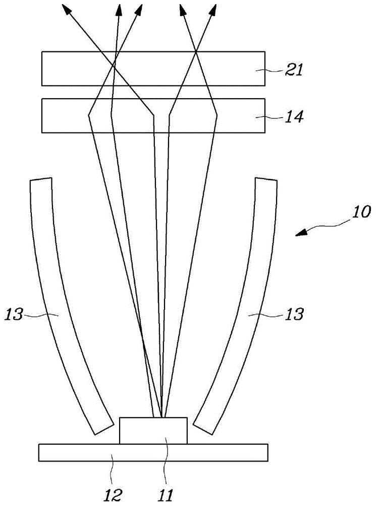
technical field [0001] The present application relates to a light source module for a lamp of a vehicle, and more particularly, to a light source module for a lamp of a vehicle that can achieve a Luminescence images of two patterns. Background technique [0002] A rear combination lamp for a vehicle is installed at the rear of the vehicle. The rear combination lamp includes a tail lamp, which is turned on during reverse gear, and a brake lamp which is turned on during braking, and a turn signal lamp. [0003] It is a development trend to apply rear combination lamps that use light emitting diodes (LEDs) with extended life and high light efficiency as light sources. Such as figure 1 As shown, the light source module 10 of the conventional rear combination lamp includes an LED light source 11, a PCB substrate 12, a reflector 13 and a light diffusion lens 14, the PCB substrate 12 controls the supply of current to the LED light source 11, and the reflector 13 will emit light ...

Claims


Application Information

Patent Timeline
IPC IPC(8): F21S8/10F21V7/22F21V13/00F21V17/00F21W101/02F21W101/14F21W101/12F21Y101/02F21W107/10
CPCF21S43/14F21S43/239F21S43/245F21S43/50F21S43/26F21S43/30F21S43/40G02B6/0025G02B6/0031G02B6/0053F21S10/00F21S41/00Y10S362/806
Inventor 梁正奎
Owner HYUNDAI MOTOR CO LTD
Learn More