Light barrier for movable light barrier switching device

A technology for switching devices and light shields, which is applied to lighting devices, fixed lighting devices, components of lighting devices, etc., can solve the problems of production noise, reduce the lifespan of light shielding plates, and block, and achieve the effect of improving lifespan and convenient and quick installation.

Inactive Publication Date: 2016-11-23
DANYANG YINUO AUTO PARTS
View PDF0 Cites 3 Cited by
  • Summary
  • Abstract
  • Description
  • Claims
  • Application Information

AI Technical Summary

Problems solved by technology

[0003] At present, most automobile companies will directly choose the projection unit in the headlight of the car, because the projection unit can adapt to different requirements of the shape, and the near and high beam functions realized by the projection unit installed on it are better than the reflective pattern alone. The realized light pattern is better, the viewing angle is wider, and the cut-off line is clearer; in order to save the space in the headlight of the car, a bifocal lens group is used, and the movable light barrier switching device installed in the bifocal lens group provides high beam and low beam switching. Switching: The switching device of the movable light baffle is composed of a solenoid valve component, a bracket and a light baffle, and the switching of the high beam and low beam functions is realized through the control of the solenoid valve component to move or rotate the light baffle. During the switching process, the existing light baffle has the following problems: 1. Friction and collision with the bracket will not only produce noise, but friction and collision will greatly reduce the life of the light barrier; 2. It cannot effectively block the light at the 50L test point, but it can be satisfied by adding features to the lens

Method used


Image

  • Light barrier for movable light barrier switching device
  • Light barrier for movable light barrier switching device
  • Light barrier for movable light barrier switching device

Examples


Embodiment Construction

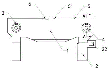
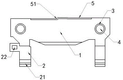
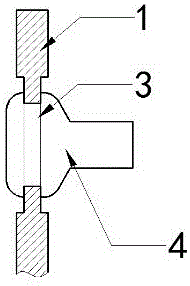
[0014] Depend on figure 1 , figure 2 , image 3 It is known that a light baffle for a movable light baffle switching device includes a light baffle main body 1. The light baffle main body 1 is an integrally formed cast aluminum part, which can quickly dissipate heat. The mounting foot 2 connected to the electromagnetic valve component is provided with a card slot 21 on the mounting foot 2, and a fixing hole 22 for connecting a return spring is also provided on the mounting foot 2 at one end. The connection between the card slot 21 on the mounting foot 2 and the movable shaft on the solenoid valve component is completed by interference fit, which is convenient and quick to install. One end of the return spring fixedly installed on the solenoid valve component is fixedly connected to the fixing hole 22 on the mounting foot 2. Inside, the two ends of the main body of the light barrier 1 are provided with a counterbore 3, and a rubber pad 4 is fixedly installed in the counterbo...


PUM


Abstract

The invention provides a light barrier for a movable light barrier switching device. The light barrier for the movable light barrier switching device comprises a light barrier body (1). The light barrier body (1) is an integrally-formed piece. Mounting feet (2) connected with electromagnetic valve components are arranged under the two ends of the light barrier body (1). Counter bores (3) are formed in the two ends of the light barrier body (1). Rubber pads (4) are fixedly mounted in the counter bores (3). The shape of the edge (5) of the upper portion of the light barrier body (1) is the same as the shape of a lower beam cut-off line, and a boss (6) is arranged at the left side of a turning point (51) of the edge (5). According to the light barrier for the movable light barrier switching device, collision or abrasion between the light barrier and a support is prevented through the rubber pads in the moving process, and thus the service life of the light barrier is greatly prolonged; light at a 50 L measuring point for a lower beam is shielded through the boss, and thus the situation that the standard requirement cannot be met due to the fact that the illuminance value of the 50 L measuring point is too high is prevented.

Description

technical field [0001] The invention relates to the technical field of automobile lamps, in particular to a light baffle for a movable light baffle switching device. Background technique [0002] With the improvement of people's living standards, more and more people have joined the ranks of car buyers, which directly promotes the development of the automobile industry. Major automobile companies have launched products with different configurations and different prices to meet different consumption needs. By. In the mid-end car market, the shape of the car is becoming more and more important, and the lights, which are the "eyes" of the car, are naturally more valued. [0003] At present, most automobile companies will directly choose the projection unit in the headlight of the car, because the projection unit can adapt to different requirements of the shape, and the near and high beam functions realized by the projection unit installed on it are better than the reflective p...

Claims


Application Information

Patent Timeline
Patent Type & Authority Applications(China)
IPC IPC(8): F21S8/10F21V14/08F21W101/02F21W101/10F21W107/10
Inventor 程葛军
Owner DANYANG YINUO AUTO PARTS
Why Eureka
Try Eureka