
Three-dimensional flow field test method based on single light-field camera

A technology of light field camera and three-dimensional flow field, which is applied in the direction of full-field flow measurement, fluid velocity measurement, and measurement devices, which can solve the problems of unsatisfactory calculation accuracy and complicated operation.

Inactive Publication Date: 2016-11-23
SHANGHAI JIAO TONG UNIV
View PDF9 Cites 22 Cited by
  • Summary
  • Abstract
  • Description
  • Claims
  • Application Information

AI Technical Summary

Problems solved by technology

However, this method is complicated to operate in actual use, and the calculation accuracy cannot meet the needs.

Method used


Image

  • Three-dimensional flow field test method based on single light-field camera
  • Three-dimensional flow field test method based on single light-field camera
  • Three-dimensional flow field test method based on single light-field camera

Examples


Embodiment Construction

[0057] A method for testing a three-dimensional velocity field of a flow field based on a single light field camera of the present invention obtains the three-dimensional velocity field distribution of the flow field through a single viewing angle measurement. Contains the following steps:

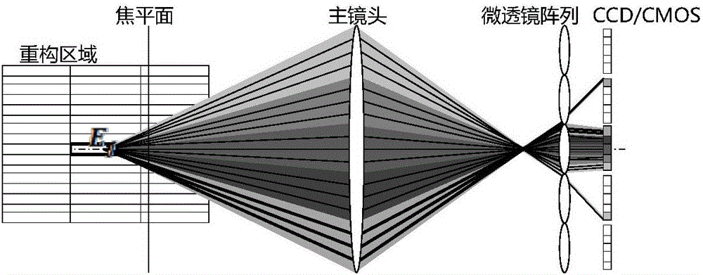
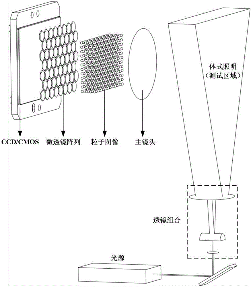
[0058] 1) Sprinkle tracer particles in the flow field to be measured (hollow glass beads of 20-30 microns are generally used in water; liquid droplets of about 1 micron or titanium dioxide particles of several hundred nanometers are generally used in air), according to figure 1 In the way of high-brightness light sources (laser, LED or high-brightness projectors) to provide body lighting; then use high-resolution or high-speed image sensors (CCD or CMOS) and micro-lens arrays (MLA) precision packages (ie light field cameras) , hereinafter referred to as a single light field camera) to capture time-series light field pictures of tracer particles.

[0059] 2) Perform preprocessing on the ca...


PUM


Abstract

The invention discloses a three-dimensional flow field testing method based on a single light field camera, A1, using a single light field camera to obtain a time series particle light field image of tracer particles in the flow field to be tested; A2, preprocessing the time series particle light field image , to remove background noise; A3, use CPU and / or GPU parallel processing methods to reconstruct time-series particle light field images to obtain time-series 3D particle images; A4, perform cross-correlation calculations on time-series 3D particle images to obtain 3D flow field velocity Field distribution; A5, post-processing the velocity field of the three-dimensional flow field, eliminating the wrong velocity vector, and replacing the eliminated wrong vector with interpolation based on the adjacent correct vector. The present invention can obtain the three-dimensional velocity distribution of the flow field to be tested through the sequential image acquisition of a single light field camera. Compared with the existing multi-view three-dimensional flow field test method, the hardware system configuration is greatly reduced and the hardware system adjustment is simplified. Steps, especially suitable for three-dimensional flow field measurement in confined space.

Description

technical field [0001] The invention belongs to the technical field of flow field observation, in particular to a three-dimensional flow field testing method based on a single light field camera. Background technique [0002] Patent application CN201210260127.8 discloses "a single CCD camera three-dimensional particle image velocity measurement method. The single CCD camera three-dimensional particle image velocity measurement technology is based on the imaging principle of a semi-convex lens. In the PIV system, the scattered light of the tracer particles is placed side by side through two The semi-convex lens forms two real images on the image plane or CCD; the distance between the two images is a function of the object distance and the optical axis distance of the two semi-convex lenses; the tracer particles can be clearly seen within the depth of field without changing the image distance In the application of the PIV system, BB1 is the distance between the images of the s...

Claims


Application Information

Patent Timeline
IPC IPC(8): G01P5/00G01P5/20G01P5/22
CPCG01P5/001G01P5/20G01P5/22
Inventor 施圣贤丁俊飞
Owner SHANGHAI JIAO TONG UNIV
Learn More