
Automatic generation method of parameterized pneumatic configuration mathematical model and structured mesh

An aerodynamic shape and automatic generation technology, applied in the direction of electrical digital data processing, special data processing applications, instruments, etc., can solve the problems of low precision, boring, and inability to use aerodynamic shape to improve the design in detail, so as to improve design efficiency and save manpower Effect

Active Publication Date: 2016-11-23
BEIJING LINJIN SPACE AIRCRAFT SYST ENG INST +1
View PDF4 Cites 16 Cited by
  • Summary
  • Abstract
  • Description
  • Claims
  • Application Information

AI Technical Summary

Problems solved by technology

These two tasks are time-consuming and tedious in the iterative process of optimizing the design of the aircraft's aerodynamic shape
[0003] In academic research, the method research on the optimal design of aerodynamic shape has already been carried out, and the research focus is on the selection and improvement of the optimization method. It can describe the corresponding shape, so the automatic generation of its mesh is also extremely simple; while the ability to automatically generate three-dimensional parametric complex shapes is limited to complex topological structures. The accuracy is lower than that of CFD, so it cannot be applied to the detailed improvement design of aerodynamic shape in engineering practice

Method used


Image

  • Automatic generation method of parameterized pneumatic configuration mathematical model and structured mesh
  • Automatic generation method of parameterized pneumatic configuration mathematical model and structured mesh
  • Automatic generation method of parameterized pneumatic configuration mathematical model and structured mesh

Examples


Embodiment Construction

[0036] The present invention will be described in detail below in conjunction with the accompanying drawings and specific embodiments.

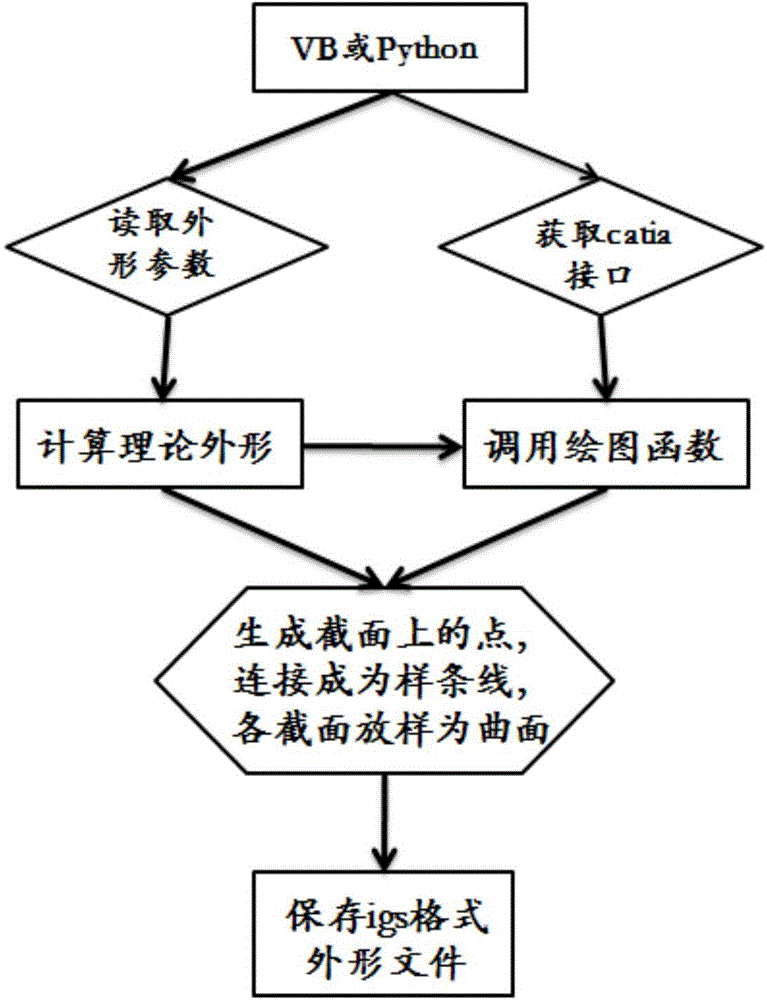
[0037] Such as figure 1 Shown in -7, the parameterized aerodynamic shape digital model of the present invention and the automatic generation method of structural grid comprise the following steps:

[0038] Step 1. Obtain the theoretical shape description of the aircraft to be optimized, and define the shape parameters. The plane of symmetry of the aircraft is given by figure 1 The 4 angle parameters shown are controlled, the position of the turning point is determined, the width of the aircraft is determined, the shape line of the upper surface of the transverse interface is an ellipse, and the lower surface is a plane, then the shape of the aircraft is determined, and the 4 angle parameters are written into the file as an input file.

[0039] Step 2. Press figure 2 The steps shown use VB or Python language to write the shape generation p...


PUM


Abstract

The invention belongs to the technical field of pneumatic configuration optimization of air vehicles and particularly relates to an automatic generation method of a parameterized pneumatic configuration mathematical model and a structured mesh. The automatic generation method comprises the following steps: acquiring theoretical configuration description of an air vehicle needing to be optimized and defining configuration parameters; writing a configuration generation program; recording operation to software by adopting a script recording method; only running a script in subsequent repeated work, so as to finish mesh generation work; adopting a digital-analog file which is consistent to a topological structure in a macro recording process and comprises a point-line-surface sequence in digital-analog; and integrating configuration automatic generation with mesh automatic generation procedures through the script of an operating system. According to the invention, theoretical configuration is calculated through reading all the parameters for defining the configuration through writing a script program, and a COM interface supplied to the Windows system through three-dimensional modeling software is obtained; and furthermore, functions of various configurations are obtained, and the functions are called to generate the digital-analog and the digital-analog is preserved.

Description

technical field [0001] The invention belongs to the technical field of aircraft aerodynamic shape optimization design, in particular to a parameterized aerodynamic shape digital model and a method for automatically generating structural grids. Background technique [0002] In the iterative process of aircraft aerodynamic shape optimization design, it is necessary to continuously adjust the shape size and evaluate the aerodynamic characteristics of the adjusted shape. In engineering practice, the generation and modification of the digital model of the aerodynamic shape of the three-dimensional complex aircraft is often completed by the designer using the existing CAD software (CATIA, ProE, UG, etc.) It is a prerequisite for the calculation of aerodynamic characteristics by CFD. Aerodynamic designers generally use pre-processing software such as Gridgen and ICEM to complete this work. At this stage, grid generation still accounts for 60% to 80% of the total manpower time of th...

Claims


Application Information

Patent Timeline
Patent Type & Authority Applications(China)
IPC IPC(8): G06F17/50
CPCY02T90/00
Inventor 苗萌周禹赵晓利闵昌万
Owner BEIJING LINJIN SPACE AIRCRAFT SYST ENG INST
Learn More