Auxiliary device for cable wiring

An auxiliary device and cable technology, applied in the direction of electrical components, etc., can solve the problems of waste of resources, waste of manpower, time-consuming, etc., and achieve the effect of avoiding repeated winding, improving work efficiency, and improving orderliness

Inactive Publication Date: 2016-11-23
LAIWU IRON & STEEL GRP
View PDF5 Cites 7 Cited by
  • Summary
  • Abstract
  • Description
  • Claims
  • Application Information

AI Technical Summary

Problems solved by technology

[0004] In the process of wrapping the cable with the spiral protective tube, the staff needs to wind it round by round, which is time-consuming and laborious
When using binding tape to bind the cables, it is necessary to bind the binding tape and the cables at intervals of one end, which takes a long time
[0005] However, when the cables or some cables are replaced, the spiral protection tube or the binding tape must be destructively removed, resulting in a large waste of resources and a lot of manpower; after the replacement is completed, it needs to be rewound Spiral protective tube or re-use binding tape for binding, time-consuming and labor-intensive

Method used


Image

  • Auxiliary device for cable wiring
  • Auxiliary device for cable wiring
  • Auxiliary device for cable wiring

Examples


Embodiment Construction

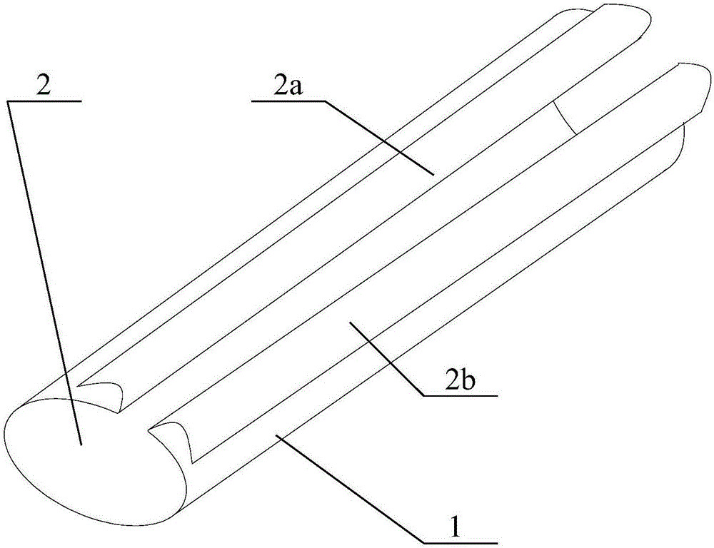
[0023] The invention discloses an auxiliary device for cable wiring, which can facilitate the protection of cables, improve work efficiency and reduce costs.

[0024] The following will clearly and completely describe the technical solutions in the embodiments of the present invention with reference to the accompanying drawings in the embodiments of the present invention. Obviously, the described embodiments are only some, not all, embodiments of the present invention. Based on the embodiments of the present invention, all other embodiments obtained by persons of ordinary skill in the art without making creative efforts belong to the protection scope of the present invention.

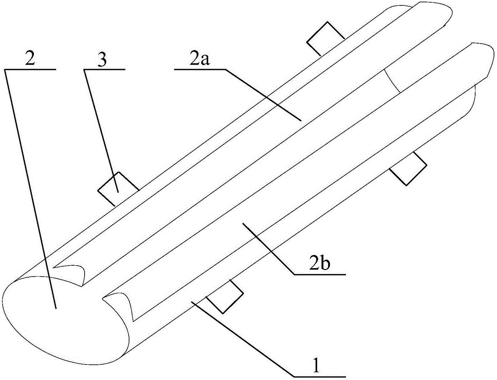
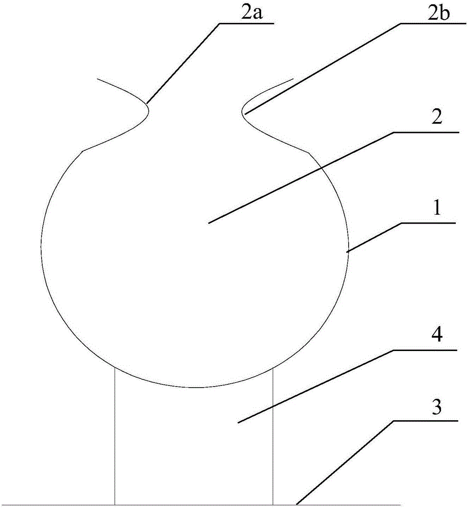
[0025] Please refer to Figure 1 to Figure 3 , figure 1 It is a schematic structural diagram of an auxiliary device for cable routing in a specific embodiment provided by the application; figure 2 It is a structural schematic diagram of another auxiliary device for cable routing in the specific imple...


PUM


Abstract

The invention discloses an auxiliary device for cable wiring. The auxiliary device comprises a main body part with a through slot, wherein the through slot is formed in the length direction of the main body part; the through slot is provided with an opening and an accommodating cavity; the extending direction of the opening is consistent with that of the through slot; a cable runs through the opening and is clamped into the accommodating cavity. In the wiring process, through application of the auxiliary device, the cable can be clamped into the accommodating cavity from the opening of the through slot, so that effects of fixing and protecting the cable are achieved, the tidiness of the cable can be improved, high time and labor consumption caused by repeated winding of a spiral protective tube and a binding tape is avoided, and the working efficiency can be improved. When the cable is required to be replaced, the cable is taken out of the accommodating cavity formed in the through slot from the opening, and the main body part is not required to be destroyed for achieving cable replacement, so that the auxiliary device can be reused, and the cost can be reduced.

Description

technical field [0001] The invention relates to the technical field of low-voltage power equipment installation, in particular to an auxiliary device for cable wiring. Background technique [0002] The existing power auxiliary equipment such as power distribution cabinets, indoor and outdoor power boxes, and operation boxes in low-power distribution rooms have complex components and tight wiring. When cables are connected to components, cables need to be wired. [0003] At present, there are generally two ways of wiring cables, one is to sheath a spiral protective tube (or cable protective sleeve) on the outer surface of the cable, and the other is to use a binding tape to bind the cables. In this way, the use of the spiral protective sleeve or the binding tape can protect the cables, and at the same time, can improve the orderliness of the cables. [0004] In the process of wrapping the cable with the spiral protective tube, the staff needs to wind it round by round, which...

Claims


Application Information

Patent Timeline
Patent Type & Authority Applications(China)
IPC IPC(8): H02G3/04
CPCH02G3/045
Inventor 程昊
Owner LAIWU IRON & STEEL GRP
Why Eureka
Try Eureka