BUCK constant voltage control circuit

A constant voltage control and circuit technology, applied in the circuit field, can solve problems such as poor chip load regulation, high solution cost, and relatively large output voltage differences, and achieve the effect of improving load regulation

Active Publication Date: 2016-11-23
SHENZHEN CHIP HOPE MICRO ELECTRONICS LTD
View PDF3 Cites 0 Cited by
  • Summary
  • Abstract
  • Description
  • Claims
  • Application Information

AI Technical Summary

Problems solved by technology

The disadvantage of this is that there will be an extra diode and capacitor in the application, and the cost of the solution is high. Second, the off-time of the chip is completely determined by the discharge speed of the peripheral capacitor C4 through the resistors R1 and R2. If the capacitor and resistor values ​​are not obtained properly, It will lead to poor load regulation of the chip, and the output voltage difference between light load and heavy load is relatively large

Method used


Image

  • BUCK constant voltage control circuit
  • BUCK constant voltage control circuit
  • BUCK constant voltage control circuit

Examples


Embodiment Construction

[0017] The present invention will be further described below in conjunction with specific drawings.

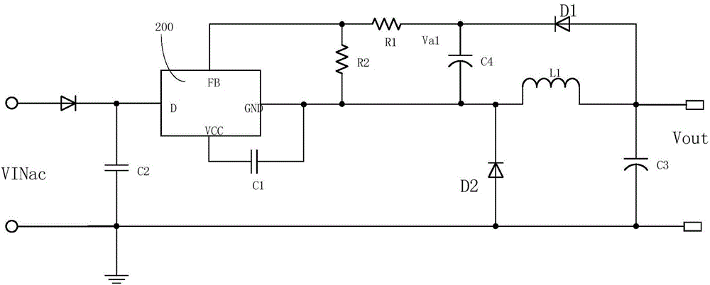
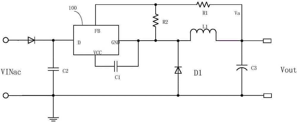
[0018] Such as image 3 As shown, the BUCK constant voltage control circuit of the present invention includes a rectifier diode D2, a control chip 100, a filter capacitor C1, a sampling resistor R1, a sampling resistor R2, an inductor L1, a freewheeling diode D1, and a capacitor C3;

[0019] Among them, such as Figure 5 As shown, the control chip 100 includes a sampling module 101, an EA module 102, an off-time control module 103, a drive unit 104, a main power switch tube Q105 and other control modules 106;

[0020] Such as image 3 As shown, the cathode of the rectifier diode D2 is connected to one end of the input capacitor C2 and the drain end of the control chip 100 ( image 3 Terminal D in the rectifier diode D2), the anode of the rectifier diode D2 and the other terminal of the input capacitor C2 are used to connect the input voltage VINac, and the other terminal of...


PUM


Abstract

The invention relates to a BUCK constant voltage control circuit. The BUCK constant voltage control circuit is characterized by comprising a rectifier diode D2, a control chip, a filter capacitor C1, a sampling resistor R1, a sampling resistor R2, an inductor L1, a free-wheeling diode D1 and a capacitor C3; the cathode of the rectifier diode D2 is connected with one end of an input capacitor C2 and a leakage end of the control chip, input voltage VINac is connected between the anode of the rectifier diode D2 and the other end of the input capacitor C2, and the other end of the input capacitor C2 is connected with the circuit ground; the source end of the control chip is internally connected with the sampling end and externally connected with one end of the sampling resistor R1 and one end of the sampling resistor R2, the other end of the sampling resistor R2 is connected with one end of the inductor L1, the cathode of the free-wheeling diode D1 and the chip ground, the other end of the sampling resistor R2 is connected with the other end of the inductor L1 and one end of the capacitor C3, and the other end of the capacitor C3 and the anode of the free-wheeling diode D1 are connected with the line ground. According to the BUCK constant voltage control circuit, the chip turn-off time is controlled by an internal control signal and not influenced by external conditions, and the load regulation is increased.

Description

technical field [0001] The invention relates to a BUCK constant voltage control circuit, in particular to a BUCK constant voltage control circuit, which belongs to the technical field of circuits. Background technique [0002] The traditional BUCK constant voltage circuit, such as figure 1 As shown, the voltage value of Va is stabilized to the value of the output voltage Vout through the diode D1 and the capacitor C4 (such as figure 2 As shown), when the FB terminal voltage of the detection chip 100 is higher than the threshold of the internal comparator, the chip 100 stops the switching action, and when it is lower than the internal comparison threshold, the switch tube is turned on. The disadvantage of this is that there will be an extra diode and capacitor in the application, and the cost of the solution is high. Second, the off-time of the chip is completely determined by the discharge speed of the peripheral capacitor C4 through the resistors R1 and R2. If the capacit...

Claims


Application Information

Patent Timeline
Patent Type & Authority Applications(China)
IPC IPC(8): H02M1/00H02M1/08
CPCH02M1/00H02M1/08H02M1/0003
Inventor 宗强刘准管磊吴寿化殷忠
Owner SHENZHEN CHIP HOPE MICRO ELECTRONICS LTD
Why Eureka
Try Eureka