
A glass clamp with adjustable automatic door closing speed

A technology of automatic door closing and glass clamping, which is applied to switches with braking devices, door/window accessories, power control mechanisms, etc. It can solve problems such as easy oil leakage, unadjustable door closing speed, and corrosion, and achieve The service life is not easy to leak oil, the speed can be adjusted at will, and the product function is stable.

Active Publication Date: 2017-12-22
NINGBO PENTAGON DAMPER CORP
View PDF9 Cites 0 Cited by
  • Summary
  • Abstract
  • Description
  • Claims
  • Application Information

AI Technical Summary

Problems solved by technology

[0002] The glass clamps on the traditional glass doors have been using ordinary hinged and spring-type glass clamps. After the glass door with ordinary hinges is opened, it must be closed manually, which is extremely inconvenient and time-consuming; Although the glass door has the function of automatic closing, it cannot control the speed of closing, because the speed of its closing is controlled by the size of the spring force, and the spring force usually rebounds quickly, making the closing speed also very fast. If the people behind are not paying attention will be hit, lack of certain security
[0003] There are some glass clamps with adjustable automatic closing speed on the market, but there are always the following problems: 1. The closing speed cannot be adjusted, either too fast or too slow; 2. The service life is not long, and it is easy to leak oil or use for a while. The closure is not in place after a period of time; 3. Because the place where the glass clip is used is relatively humid and easy to rust or be corroded, some parts of the product will rust or be corroded after a period of use, seriously affecting the performance and appearance.

Method used


Image

  • A glass clamp with adjustable automatic door closing speed
  • A glass clamp with adjustable automatic door closing speed
  • A glass clamp with adjustable automatic door closing speed

Examples


Embodiment Construction

[0026] The following will clearly and completely describe the technical solutions in the embodiments of the present invention with reference to the accompanying drawings in the embodiments of the present invention. Obviously, the described embodiments are only some, not all, embodiments of the present invention. All other embodiments obtained by persons of ordinary skill in the art based on the embodiments of the present invention belong to the protection scope of the present invention.

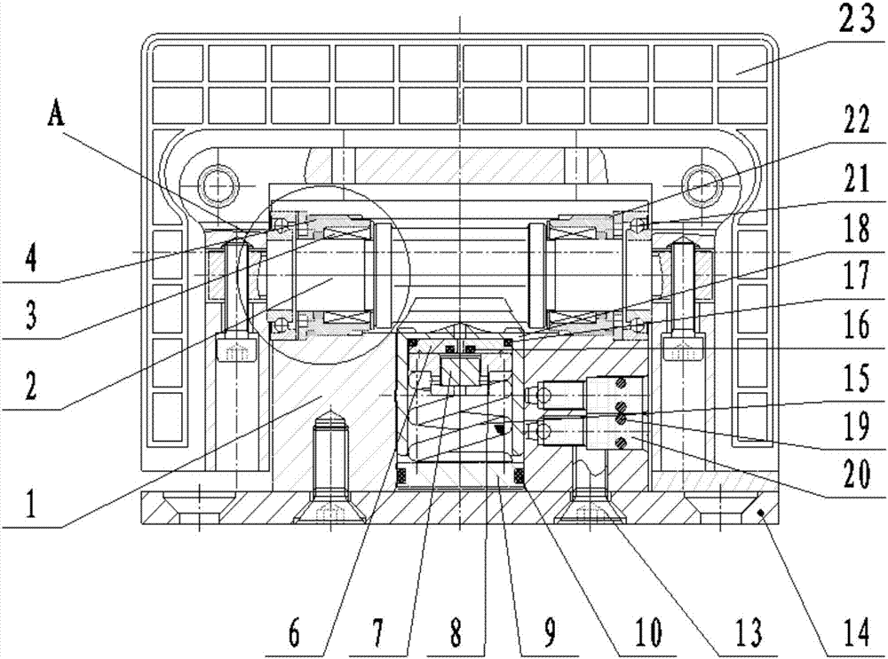
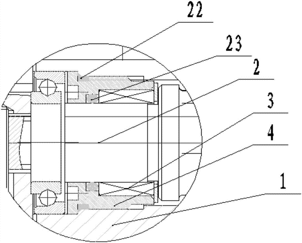
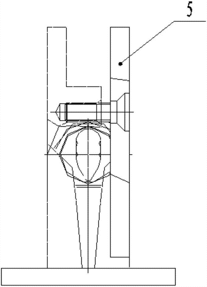
[0027] Such as Figure 1-8 As shown, a glass clamp with adjustable automatic door closing speed according to an embodiment of the present invention includes a hydraulic glass clamp and a spring glass clamp matched with the hydraulic glass clamp. The hydraulic glass clamp includes a first panel 5 and a hydraulic glass clamp. A fixed clip 23, a hydraulic fixed seat 1 is arranged between the first panel 5 and the hydraulic fixed clip 23, and a hydraulic cam assembly, a hydraulic piston assembly ...


PUM


Abstract

The invention discloses a glass clamp with adjustable automatic door closing speed, which includes a hydraulic glass clamp and a spring glass clamp matched with the hydraulic glass clamp. The hydraulic glass clamp includes a first panel and a hydraulic fixing clip. The first A hydraulic fixing seat is arranged between the panel and the hydraulic fixing clip, and a hydraulic cam assembly, a hydraulic piston assembly and a speed regulating valve are arranged in the hydraulic fixing seat; the spring glass clip includes a second panel and a spring fixing clip, so A spring fixing seat is arranged between the second panel and the spring fixing clip, and a spring cam assembly and a spring piston assembly are arranged in the spring fixing seat. Beneficial effects of the present invention: reasonable structure, simple installation, positioning, automatic door closing, hydraulic buffering, windproof and hand-clamping, speed can be adjusted at will, long service life and not easy to leak oil, and every detail has super antirust and corrosion resistance The function of the product is stable, practical and durable.

Description

technical field [0001] The invention relates to the technical field of glass door clips, in particular to a glass clip with adjustable automatic door closing speed. Background technique [0002] The glass clamps on the traditional glass doors have been using ordinary hinged and spring-type glass clamps. After the glass door with ordinary hinges is opened, it must be closed manually, which is extremely inconvenient and time-consuming; Although the glass door has the function of automatic closing, it cannot control the speed of closing, because the speed of its closing is controlled by the size of the spring force, and the spring force usually rebounds quickly, making the closing speed also very fast. If the people behind are not paying attention Will be hit, lack of certain security. [0003] There are some glass clamps with adjustable automatic closing speed on the market, but there are always the following problems: 1. The closing speed cannot be adjusted, either too fast ...

Claims


Application Information

Patent Timeline
Patent Type & Authority Patents(China)
IPC IPC(8): E05F15/49E05F15/50
CPCE05F3/104E05D5/0246E05F3/12E05Y2600/12
Inventor 蔡赋勇
Owner NINGBO PENTAGON DAMPER CORP
Learn More