Security RAM block with multiple partitions

An area, memory block technology used in instrumentation, preventing unauthorized use of memory, computing, etc.

Active Publication Date: 2016-11-30
INTEL CORP
View PDF6 Cites 4 Cited by
  • Summary
  • Abstract
  • Description
  • Claims
  • Application Information

AI Technical Summary

Problems solved by technology

If the key is stored in memory for use during decryption, it is desirable to protect and restrict access to the key

Method used


Image

  • Security RAM block with multiple partitions
  • Security RAM block with multiple partitions
  • Security RAM block with multiple partitions

Examples


Embodiment Construction

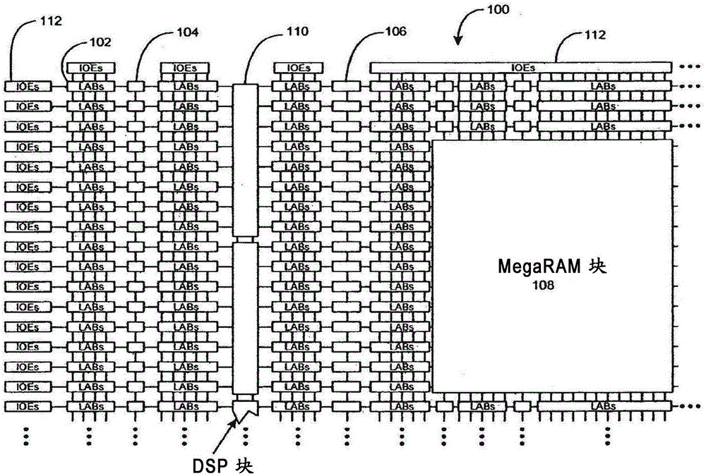
[0041] figure 1 is a simplified partial block diagram of an exemplary high density programmable logic device 100 in which techniques according to the present invention may be used. PLD 100 includes a two-dimensional array of programmable logic array blocks (LABs) 102 interconnected by a network of variable length and speed row and column interconnects. LAB 102 includes a number (eg, 10) of logic elements (LEs), which are small logic units that provide efficient implementation of user-defined logic functions.

[0042] PLD 100 also includes a distributed memory structure that includes variable sized RAM blocks provided throughout the array. The RAM blocks include, for example, a 512-bit block 104, a 4K block 106, and an M-block 108 providing 512K bits of RAM. These memory blocks may also include shift registers and FIFO buffers. The PLD 100 also includes a digital signal processing (DPS) block 110 that may implement, for example, a multiplier with addition and subtraction fe...


PUM


Abstract

The disclosure relates to a security RAM block with multiple partitions. Circuits, methods, and apparatus for storing application data, keys, authorization codes, or other information in a volatile memory on an FPGA. A field programmable gate array (FPGA) can include multiple memory blocks and partition those blocks among multiple independent reconfigurable regions. Access to the memory blocks can then be restricted so that only authorized regions have access to particular memory partitions. In addition, each partition can store multiple message authentication codes (MACs) for further controlling access to data in each partition.

Description

[0001] Cross References to Related Applications [0002] This application is a continuation-in-part of U.S. Patent Application Serial No. 12 / 830,447, filed June 6, 2010, which was filed September 7, 2006, entitled "SECURITY RAM BLOCK" US Patent Application No. 11 / 517,689 (now US Patent No. 7,752,407), all of which are incorporated herein by reference in their entirety. Background technique [0003] The present invention relates generally to storing data on integrated circuits, and more particularly to protecting data stored in battery-backed memory on field programmable gate arrays (FPGAs). [0004] The circuit complexity and tasks performed by integrated circuits, such as field programmable gate arrays, have increased enormously over the past few years. Highly complex software or applications configured to perform complex user-defined functions run on programmable logic elements. [0005] Typically, these applications require data to be stored in memory, eg, applications m...

Claims


Application Information

Patent Timeline
Patent Type & Authority Applications(China)
IPC IPC(8): G06F12/14G06F21/76G06F21/79G06F21/81
CPCG06F21/76G06F2221/2141G06F2221/2143G06F12/1416G06F21/79G06F21/81
Inventor M·朗哈默
Owner INTEL CORP
Why Eureka
Try Eureka