Broadband active multi-beam antenna system and correction method thereof

A multi-beam antenna and active antenna technology, which is applied to antennas, antenna arrays, electrical components, etc., can solve the problems of reduced engineering realizability, small dynamic range, increased weight, cost, and power consumption, and improve engineering Achievability, reduction of system equipment, cost and power consumption reduction effects

Active Publication Date: 2016-11-30
CHINA ELECTRONIC TECH GRP CORP NO 38 RES INST
View PDF4 Cites 7 Cited by
  • Summary
  • Abstract
  • Description
  • Claims
  • Application Information

AI Technical Summary

Problems solved by technology

The three methods have their own advantages and disadvantages. The error and distortion introduced by analog beamforming are large, but the performance is acceptable; digital beamforming has high flexibility, but there are problems such as timing, jitter and power consumption; optical beamforming can achieve greater Bandwidth, but less dynamic range and less stability
[0005] In the process of realizing the present invention

Method used


Image

  • Broadband active multi-beam antenna system and correction method thereof
  • Broadband active multi-beam antenna system and correction method thereof
  • Broadband active multi-beam antenna system and correction method thereof

Examples


Embodiment Construction

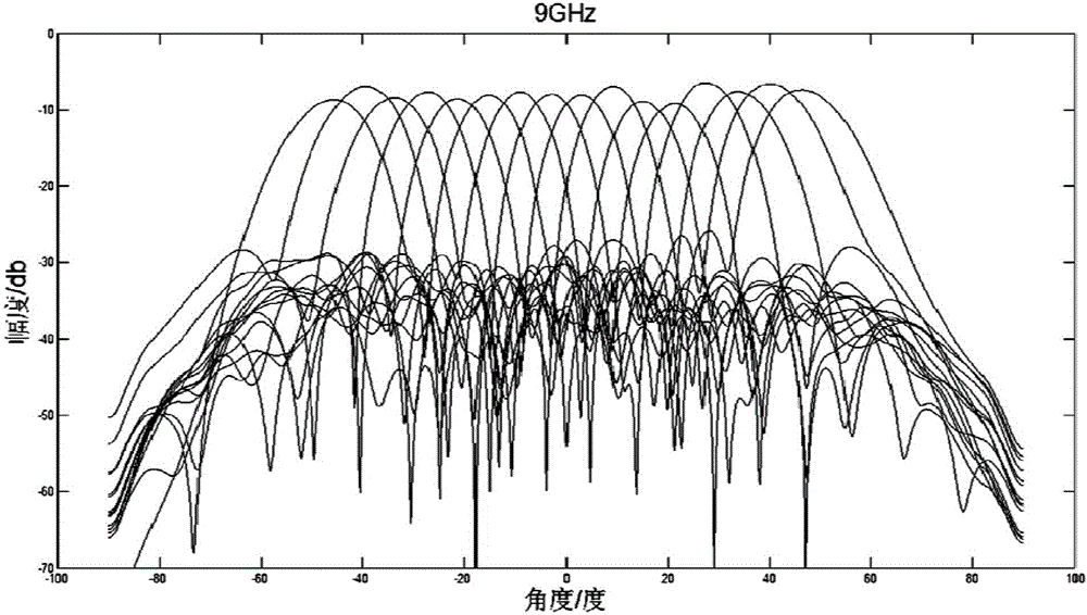
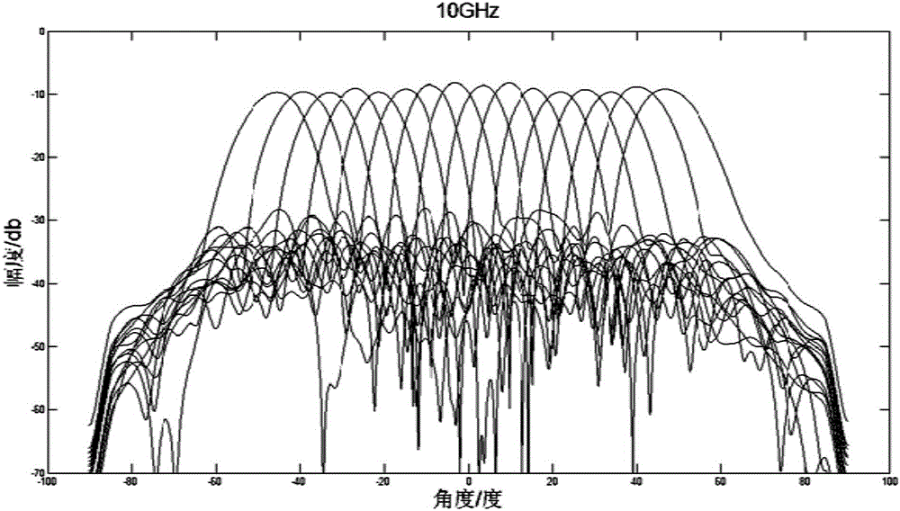
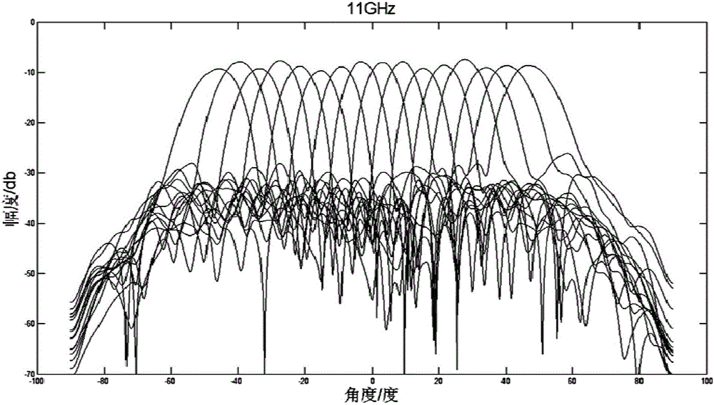
[0026] Such as image 3 , 4 , 5, the present invention will be described in detail below in conjunction with the accompanying drawings.

[0027] A broadband active multi-beam antenna system, comprising a broadband active antenna array 1 and a multi-beam network 2, the broadband active antenna array 1 and the multi-beam network 2 are connected by a radio frequency cable 14;

[0028] Preferably, the broadband active antenna array 1 comprises at least two column line sources 11 and a multifunctional radio frequency front end 12 and a control unit 13, wherein the column line source 11 and the multifunctional radio frequency front end 12 are integrated by blind matching, and the column line The source 11 receives multiple radio frequency signals and performs pitch synthesis; the multi-functional radio frequency front end 12 performs low-noise amplification, filtering, amplitude weighting and phase shift processing on the radio frequency signals output by the line source 11; the co...


PUM


Abstract

The invention relates to the field of broadband array antennas, in particular to a broadband active multi-beam antenna system, which comprises a broadband active antenna array and a multi-beam network, wherein the broadband active antenna array comprises at least two column line sources and multifunctional radio-frequency front ends and a control unit; the column line sources receive multiple paths of radio-frequency signals and carry out pitching direction synthesis; the multifunctional radio-frequency front ends carry out low-noise amplifying, filtering, amplitude weighting and phase shift processing on the radio-frequency signals output by the column line sources; the control unit receives a control instruction input from the outside and adjusts attenuation and phase shift code values in the multifunctional radio-frequency front ends; and the multi-beam network synthesizes the radio-frequency signals output by the multifunctional radio-frequency front ends on the basis of lens network implementation and simultaneously outputs multiple paths of beams in an azimuth direction. A near field diameter inversion correction method is adopted by the broadband active multi-beam antenna system. Compared with a broadband multi-beam system formed by digital beams, the broadband active multi-beam antenna system has the advantages that the equipment quantity is greatly reduced, the weight, the cost and the power consumption are greatly reduced and the broadband active multi-beam antenna system is easily applied to engineering.

Description

technical field [0001] The patent of the present invention relates to the field of broadband array antennas, especially the broadband active antenna system in the electronic surveillance system, specifically the broadband active multi-beam antenna system. Background technique [0002] In order to adapt to the detection and reception of various electronic signals under complex electromagnetic environment conditions, an array antenna system that can meet the technical requirements of high gain, large instantaneous bandwidth, and wide airspace coverage is urgently needed. The broadband active multi-beam antenna system can form multiple receiving beams at the same time, realize large-angle scanning through rapid beam scheduling, and integrate broadband active circuits inside the array antenna, which can realize high-gain detection under large bandwidth conditions. Therefore, broadband active multi-beam antenna systems are widely used in electronic surveillance systems. [0003]...

Claims


Application Information

Patent Timeline
IPC IPC(8): H01Q3/28H01Q3/34H01Q21/00H01Q23/00
CPCH01Q3/28H01Q3/34H01Q21/00H01Q23/00
Inventor 向海生杨宇宸卢晓鹏万笑梅余峰刘浩莫骊张琦
Owner CHINA ELECTRONIC TECH GRP CORP NO 38 RES INST
Why Eureka
Try Eureka