A milling tool
一种铣刀、切削刀片的技术,应用在铣刀、铣削切削刀片、切削刀片等方向,能够解决切削刀片更换繁琐且费时、转位工作费时等问题
- Summary
- Abstract
- Description
- Claims
- Application Information
AI Technical Summary
Problems solved by technology
Method used
Image
Examples
Embodiment Construction
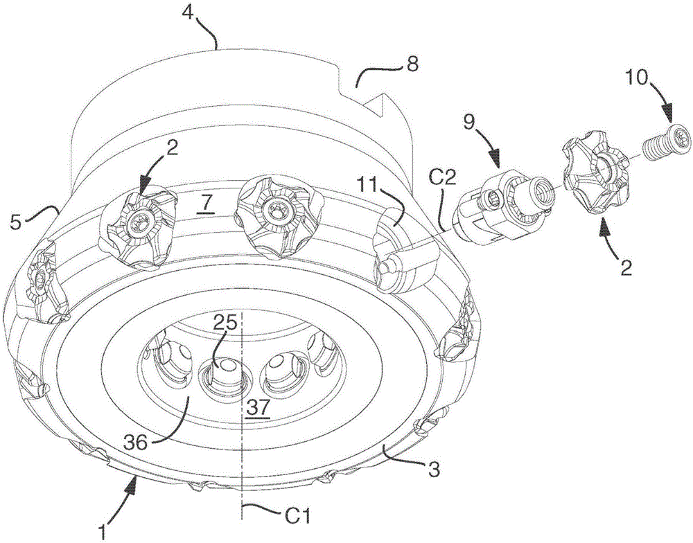
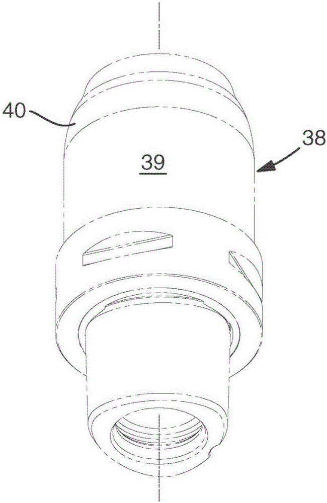
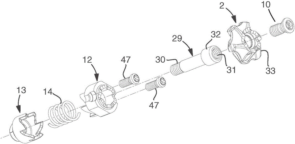
[0032] In the figures, a cutting tool made according to the invention is shown in the form of a face mill or end mill. In the tool there is comprised a body or body generally designated 1 which houses a plurality of replaceable cutting inserts 2 . Body 1 includes a pair of opposite fronts 3 and backs 4 (see figure 1 and 9) and an envelope surface 5 located between the front side 3 and the rear side 4 and having a circular rotationally symmetrical shape. The front side 3, the envelope side 5 and the back side 4 are contained in the outer side of the body. The back face 4 is a flat annular surface. The front face 3 is also a flat annular surface, which in this example extends perpendicular to the central axis C1 on which the body is rotatable. Surfaces 3 and 4 are parallel to each other and also to the reference plane RP, which at Figure 9 shown in . It should additionally be noted that the surface of revolution forming the envelope surface 5 is generated on the central a...
PUM
 Abstract
Description
Claims
Application Information
 - R&D
- Intellectual Property
- Life Sciences
- Materials
- Tech Scout
- Unparalleled Data Quality
- Higher Quality Content
- 60% Fewer Hallucinations
Browse by: Latest US Patents, China's latest patents, Technical Efficacy Thesaurus, Application Domain, Technology Topic, Popular Technical Reports.
© 2025 PatSnap. All rights reserved.Legal|Privacy policy|Modern Slavery Act Transparency Statement|Sitemap|About US| Contact US: help@patsnap.com


