
Pedicle screw positioning and guiding device

A positioning-guided, pedicle screw technology, applied in the field of medical devices, can solve the problems of increasing the radiation dose of patients and medical staff, increasing the exposure of surgical rays, increasing the complexity of surgery, etc., to facilitate cleaning and disinfection, reduce operation time, Ease of promoting the effect of the application

Active Publication Date: 2016-12-07
陈春美 +4
View PDF9 Cites 9 Cited by
  • Summary
  • Abstract
  • Description
  • Claims
  • Application Information

AI Technical Summary

Problems solved by technology

[0006] This is currently the most common practice in clinical practice. However, this method has large errors, and it needs to refer to the X-ray fluoroscopy images during the operation to constantly correct the actual nail insertion route, which will greatly increase the complexity of the operation and increase the operation time. Radiation exposure increases the operating time and puts high demands on the surgeon
[0007] In addition, if multiple X-ray fluoroscopy is performed during the operation, the radiation dose of patients and medical staff will be increased, which will cause harm to the human body.
[0008] The other is intraoperative positioning and navigation, which is one of the most advanced positioning methods in the world. It can know the real-time information of the probe position and guide precise surgery. However, it is expensive and difficult to popularize. Ordinary municipal hospitals, Most county-level hospitals are unable to purchase

Method used


Image

  • Pedicle screw positioning and guiding device
  • Pedicle screw positioning and guiding device
  • Pedicle screw positioning and guiding device

Examples


Embodiment Construction

[0040] The content of the present invention will be described in detail below in conjunction with the accompanying drawings and specific embodiments of the description:

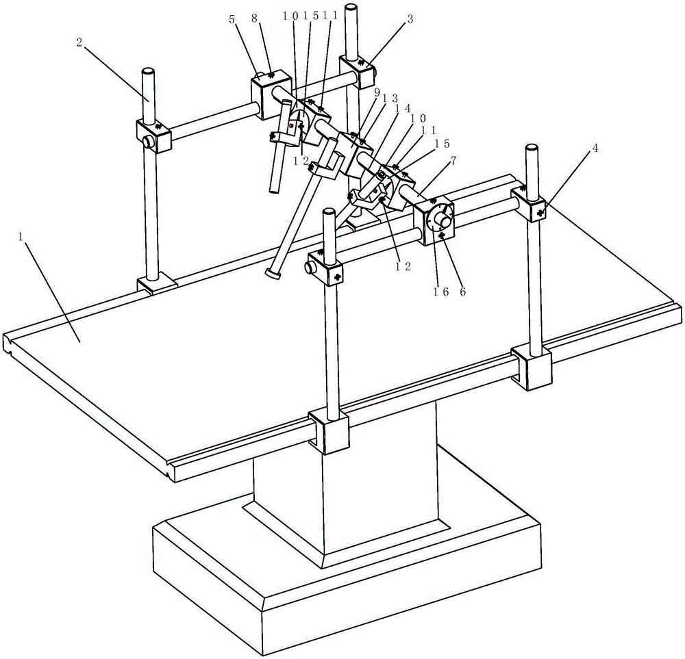
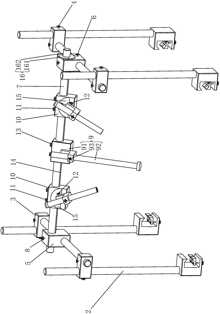
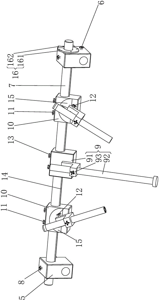
[0041] Such as figure 1 - Figure 8As shown, a pedicle screw positioning and guiding device provided by the present invention includes a frame 2 fixed on the hospital bed 1, a lifting frame 3 that is slidably connected to the frame 2 and can slide up and down relative to the frame 2, Locking device-4 for restricting the vertical sliding of the lifting frame 3 relative to the frame 2 between the lifting frame 3 and the frame 2, a sliding frame 5 that is slidably connected to the lifting frame 3 and can move back and forth relative to the lifting frame 3, Be arranged between sliding frame 5 and elevating frame 3 and be used to limit sliding frame 5 to move forward and backward relative to elevating frame 3 locking device two 6, be connected to the rotating rod 7 on sliding frame 5 in rotation, be arranged on s...


PUM


Abstract

The invention relates to the field of medical instruments, in particular to a pedicle screw positioning and guiding device. The pedicle screw positioning and guiding device comprises a rack, a lifting frame, a first locking device, a sliding frame, a second locking device, a rotation rod, a third locking device, a distance measuring device and two guiders. Each guider comprises a sliding block and a guiding cylinder. The distance measuring device comprises an installation base and a measuring scale. The axis of the measuring scale is perpendicular to the axis of the rotation rod. The axis of the measuring scale and the axes of the guiding cylinders are located on the same plane. The axis of each guiding cylinder hinged shaft is perpendicular to the plane where the axis of the corresponding guiding cylinder is located. The positioning and guiding device further comprises a fourth locking device, a fifth locking device, a sixth locking device, a positioning linkage device, a first angle measuring device and a second angle measuring device. The positioning and guiding device can adjust the guiders to the position which is worked out through a computer in three-dimensional space, and therefore a pedicle screw is guided, accurate implanting of the pedicle screw is achieved, the device is precise in positioning, and the manufacturing cost is low.

Description

technical field [0001] The invention relates to the field of medical instruments, in particular to a pedicle screw positioning and guiding device. Background technique [0002] Pedicle screws play an important role in the treatment of spinal trauma reduction and deformity correction, and the key to the success of pedicle screw internal fixation is whether the screw can be accurately inserted through the pedicle without damaging the nerve vertebral body . [0003] How to accurately control the position, direction and angle of the pedicle screw during the operation determines whether it can enter the vertebral body smoothly, which involves the positioning and guidance of the pedicle screw. [0004] The current methods for pedicle screw positioning can be divided into two categories: [0005] One is preoperative positioning, which uses preoperative CT and MRI scans to determine the location of the lesion, and then relies on the professional knowledge of the doctor to plan the...

Claims


Application Information

Patent Timeline
IPC IPC(8): A61B17/90A61B17/70
CPCA61B17/70A61B17/88A61B17/90
Inventor 陈春美庄源东赵伟沈超雄蔡昭文蔡然泽傅超锋吴剑锋康成栋王锐李峰陈靖王殷庆蔡钢锋张伟强韦浩
Owner 陈春美
Learn More