Part bending device for electric equipment

A technology for power equipment and bending processing, applied in the field of bending devices, can solve problems such as the use stability of the precision equipment that is not conducive to processing, the flexible deformation of the extension length of the bending execution head, the increase of equipment cost and complexity, etc. The effect of post-maintenance, improving reliability and service life, and reducing equipment complexity

Inactive Publication Date: 2016-12-07
吴三红
View PDF7 Cites 1 Cited by
  • Summary
  • Abstract
  • Description
  • Claims
  • Application Information

AI Technical Summary

Problems solved by technology

As a result, the cost and complexity of the equipment are increased, and it is not convenient for later maintenance
In addition, in machines that use thread-driven bending, excessive extension length of the bending execution head will easily cause defects such as flexible deformation, which is not conducive to the accuracy of processing and the stability of the equipment.

Method used


Image

  • Part bending device for electric equipment

Examples


Embodiment Construction

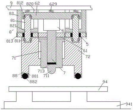
[0007] Combine below figure 1 The present invention will be described in detail.

[0008] The bending processing device for parts for electric equipment according to the embodiment is used for bending processing for parts for electric equipment, including two lifting and pressing assemblies 8 fixedly installed on the upper fixture 9, and the two lifting and pressing assemblies 8 are arranged symmetrically with respect to the longitudinal axis of the bending device and each includes: a threaded sleeve 82 fixed on the upper fixture 9, a driving screw threadedly engaged with the threaded hole 821 in the lower end wall of the threaded sleeve 82 81, and the screw drive gear 813 located under the threaded sleeve 82 and connected with the drive screw 81 through the torque clutch 5, the lower end of the drive screw 81 of each of the two lifting and pressing assemblies 8 passes through the lower end The thrust bearing 811 is connected to the upper side of the workpiece pressing part 7...


PUM


Abstract

A bending processing device for parts for electric equipment, used for bending processing for parts for electric equipment, including two lifting and pressing components (8) for fixing and installing on the upper fixing object (9), the two lifting and lowering components The pressing components (8) are arranged symmetrically with respect to the longitudinal axis of the bending device and each includes: a threaded sleeve (82) fixed on the upper fixture (9), and a lower end wall of the threaded sleeve (82) The threaded hole (821) in the threaded drive screw (81), and the screw drive gear ( 813).

Description

technical field [0001] The bending device of the present invention is specifically a bending processing device for parts used in electric equipment. Background technique [0002] In power equipment, due to various needs such as cable fixing and electrical component positioning and installation, bending parts with different shapes are usually required. The bending of such parts is often processed by bending machines. Traditional bending machines often use methods such as stamping or molding. During the bending process, in order to ensure the accuracy of the processed shape, it is necessary to perform a pressing operation on the edge of the workpiece. This often requires a separate blank holder drive to perform. This increases the cost and complexity of the equipment, making it inconvenient for later maintenance. In addition, in machines that use thread-driven bending, excessive extension of the bending actuator will easily cause defects such as flexible deformation, which...

Claims


Application Information

Patent Timeline
IPC IPC(8): B21D5/01B21D43/00B30B1/18
CPCB21D5/01B21D43/003B30B1/181
Inventor 吴三红
Owner 吴三红
Why Eureka
Try Eureka