
Handle saw web and sawtooth machining process

A processing technology and saw blade technology, applied in the field of handle saw blade sawtooth processing technology, can solve the problems that powder cannot be recycled, reduce the precision of handle saw blade, shorten the service life of grinding wheel, etc., so as to reduce the workload and structure of grinding wheel. Simple, low processing cost effect

Inactive Publication Date: 2016-12-07
CHONGQING MINGYOU STEEL PROD MFG CO LTD
View PDF7 Cites 10 Cited by
  • Summary
  • Abstract
  • Description
  • Claims
  • Application Information

AI Technical Summary

Problems solved by technology

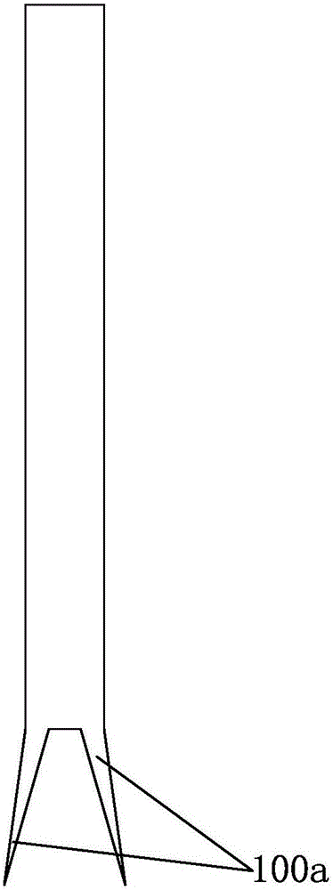
[0004] The defects of the above-mentioned process are: 1. Since the sawtooth 100a is stamped one by one, the cumulative error will be caused, thereby reducing the accuracy of the handle saw blade; More than 10cm, which in turn reduces the processing efficiency; 2. The existing process is complex, with many process steps, low processing efficiency, high labor intensity of workers, and high cost
[0006] Although the above-mentioned process method effectively reduces the cumulative error of the original processing technology, it still has the following defects: 1. Since the sawtooth and the edges on both sides of the sawtooth are hard-grinded by the grinding wheel of the CNC gear grinding machine, this will cause greater wear of the grinding wheel , which not only shortens the service life of the grinding wheel, but also greatly increases the manufacturing cost, and the wear of the grinding wheel will also produce cumulative errors, which will still interfere with the subsequent tooth division steps; 2. Due to the wear of the grinding wheel, there will still be cumulative errors Therefore, when dividing the teeth, the whole saw blade 100 cannot be divided into teeth at one time, and the efficiency of dividing the teeth needs to be improved; mouth, this part of the ground powder cannot be recycled and reused, resulting in a waste of resources

Method used


Image

  • Handle saw web and sawtooth machining process
  • Handle saw web and sawtooth machining process
  • Handle saw web and sawtooth machining process

Examples


Embodiment Construction

[0041] Below in conjunction with accompanying drawing and embodiment the present invention will be further described:

[0042] Such as figure 1 , 2 , Shown in 3, 4 and 5, a kind of handle saw blade sawtooth processing technology is characterized in that comprising the following steps:

[0043] Step a: The saw blade 100 is formed, specifically, the saw blade is flattened, and the specific process steps are the same as the existing process steps.

[0044] Step b: Use the first punch to punch out a group of saw teeth 100a arranged along the length direction of the saw blade on the saw blade 100. These saw teeth 100a are on the same plane, and a stamping head of the first punch is fixed with a A mould, the shape of which matches the shape of the sawtooth 100a.

[0045] Step c: Grinding both sides of each sawtooth 100a with a CNC gear grinding machine to form a cutting edge. When grinding the gear, it is automatically controlled by the program of the CNC gear grinding machine, ...


PUM


Abstract

The invention discloses a sawtooth processing technology of a handle saw blade, which is characterized in that it comprises the following steps: step a: shaping the saw blade (100); step b: punching out a set of edges on the saw blade (100) The saw teeth (100a) arranged in the lengthwise direction of the saw blade; step c: use a CNC gear grinding machine to grind both sides of each saw tooth (100a) to form a cutting edge; step d: deburring and polishing. The upper and lower sides of (100) are deburred and polished; step e: divide the teeth, in this step, the second punch press is used to press the saw blade (100), so that all the saw teeth (100a) on a piece of saw blade (100) ) to complete the tooth division at one time. This process method effectively simplifies the process, greatly improves the processing efficiency and precision, effectively eliminates the cumulative error, and reliably reduces the processing cost. The waste produced after stamping can also generate a certain economic value, thus effectively overcoming the existing process method. disadvantages, has good practicality.

Description

technical field [0001] The invention belongs to the field of handle saw blade production, and in particular relates to a process for processing saw teeth of a handle saw blade. Background technique [0002] Such as figure 1 , 2 As shown, the handle saw blade 100 is a widely used hardware tool, which is provided with a set of elongated saw teeth 100a, and cuts objects through the cutting edge of the saw teeth 100a. Moreover, the odd number of saw teeth 100a are inclined to one side of the handle saw blade 100 , and the even number of saw teeth 100a are inclined to the other side of the handle saw blade 100 . [0003] The most primitive sawtooth processing process of the handle saw blade is as follows: a. Polish the handle saw blade 100; b. Punch the teeth of the handle saw blade 100 along the length direction with a punching machine one by one to form saw teeth 100a one by one; c. 1. Grinding the sawtooth 100a one by one by hand, thereby forming a cutting edge on both side...

Claims


Application Information

Patent Timeline
Patent Type & Authority Applications(China)
IPC IPC(8): B23D65/02
CPCB23D65/02
Inventor 陈明友
Owner CHONGQING MINGYOU STEEL PROD MFG CO LTD
Learn More