Bottom surface sanding machine

A technology of sanding machine and bottom surface, which is applied in the field of sanding machines, can solve the problems of inability to directly match plates of different thicknesses, increase the cost of purchasing machines, increase production costs of enterprises, and large space limitations, and achieve simple structure, low cost, and matching flexible effects

Inactive Publication Date: 2016-12-07
ANJI DEMAI BAMBOO & WOOD MACHINERY
View PDF7 Cites 0 Cited by
  • Summary
  • Abstract
  • Description
  • Claims
  • Application Information

AI Technical Summary

Problems solved by technology

[0003] If you want to avoid the process of flipping the plate, you need to add an existing bottom sander. The worktable of the sander is on the top and the sand frame is on the bottom. Also, the worktable moves up and down to adapt to different thicknesses. Plates, but because different plates have different thicknesses and can only be raised and lowered by the workbench, the top sander and bottom sander cannot directly match plates of different thicknesses. It is necessary to add two ends and two machines between the two machines The hinged length is at least longer than the length of the plate (at least two to three meters in length), which not only makes the whole set of equipment occupy a large area, but also greatly increases the cost
Now there are also some integrated whole machine plates that can be directly sanded on both sides, but the cost of this equipment is much higher than the current top sander or bottom sander, and most of the small factories have the original top sander It will be discarded, which not only causes a waste of resources, but also increases the production cost of the enterprise due to the large purchase cost. Generally, small factories will choose to use the original equipment

Method used


Image

  • Bottom surface sanding machine
  • Bottom surface sanding machine
  • Bottom surface sanding machine

Examples


Embodiment 1

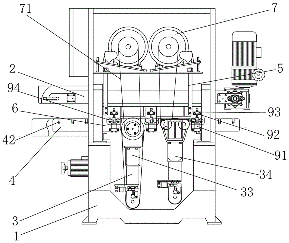
[0031] A bottom surface sanding machine, comprising a frame 1, a workbench 2 arranged on the frame, a sand frame 3 and a sand frame motor 7, the bottom surface of the workbench is a working surface, and a lifting assembly is arranged under the workbench An elevating platform 4 that can move up and down along the frame, and the sand frame is fixed on the elevating platform.

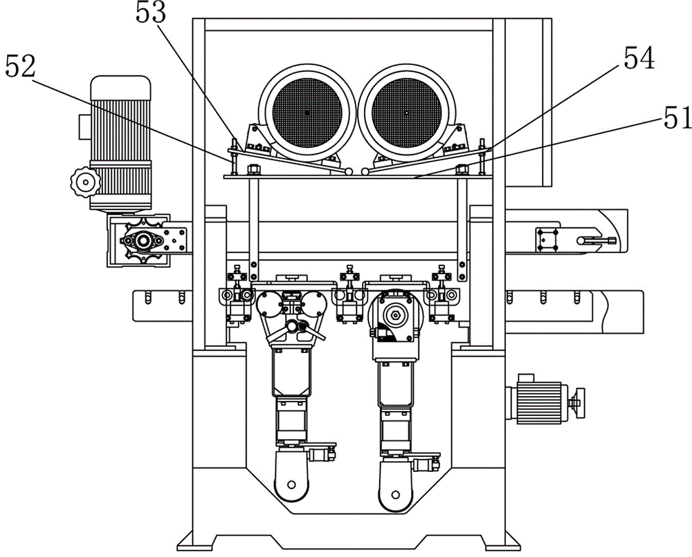
[0032] The sand frame motor is erected on the top of the workbench through the frame rod 5 whose bottom end is fixed on the lifting platform. The sand frame motor is hung on the top of the worktable through the frame rod, so as to save space without increasing the height of the entire lifting platform, and has a compact structure.

[0033] Mounting plates 6 are fixed on both sides of the middle part of the lifting platform, a pressing assembly is arranged on the mounting plate, and the frame rod is fixed on the mounting plate. There is a frame rod on the outer surface of both ends of the mounting plate on...

Embodiment 2

[0037]The difference from the above embodiment is that the sand frame of this embodiment includes a front sand frame 33 and a rear sand frame 34, and the sand frame installation grooves are two for installing the front sand frame and the rear sand frame respectively, and one can also be set according to the requirement Or three or more sand frames and suitable sand frame installation grooves; in the present embodiment, at least one set of pressing assembly is provided between the front side of the front sand frame, the rear side of the rear sand frame, and the front and rear sand frames, so that For the stable transfer of the sheet. A reinforcing connecting plate 611 is also fixedly connected between the connecting hanging plate and the mounting plate; the lifting table includes a feeding section at both ends with several feeding rollers 42, and a feeding section in the middle with The working section of the grinding through hole 43 of the abrasive belt on the sand frame and t...

Embodiment 3

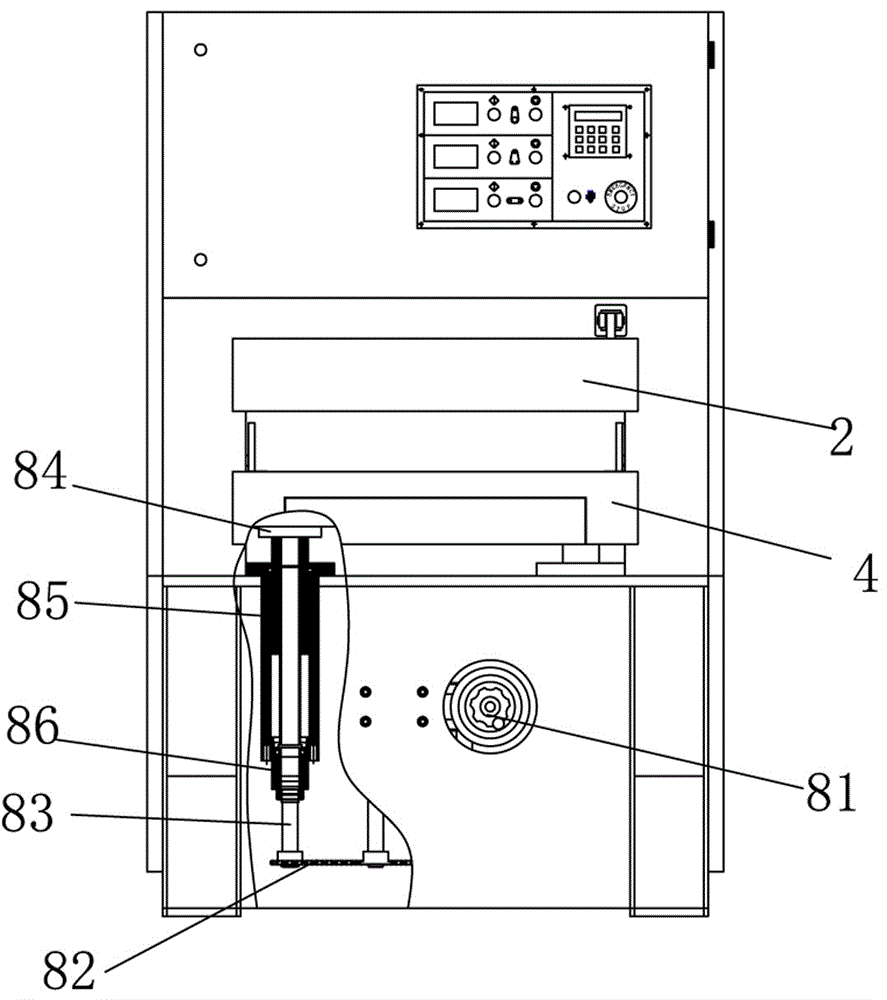
[0041] The difference from the above embodiment is that the lifting assembly includes a lifting motor 81 arranged in the frame, a lifting shaft 83 that is connected to the main shaft of the lifting motor through a transmission chain 82, and a lifting shaft 83 that is screwed to the side of the lifting shaft. The seat 84 is fixed on the frame and is sleeved on the lifting sleeve 85 on the lifting seat.

[0042] The lower end of the lifting sleeve is provided with a stable guide seat 86 that is socketed with the lifting shaft through a bearing. A sleeve between the lifting shafts and having an internal thread screwed with the lifting shaft, the length of the sleeve is less than or equal to the distance from the top of the lifting sleeve to the top of the stable guide seat. The length of the lifting shaft is long and easy to twist, and the upper part is screwed with the bushing to have a torque, and the bottom is connected to the lifting chain and there is another torque. The two...


PUM


Abstract

The invention belongs to the field of sanding machines, and particularly relates to a bottom surface sanding machine. The bottom surface sanding machine comprises a machine frame, a workbench, sanding racks and sanding rack motors, wherein the workbench, the sanding racks and the sanding rack motors are arranged on the machine frame. The bottom face of the workbench is a working face. A lifting platform capable of moving up and down along the machine frame through a lifting assembly is arranged below the workbench. The sanding racks are fixedly arranged on the lifting platform. The sanding rack motors are erected above the workbench through rack rods with the bottom ends fixedly arranged on the lifting platform. According to the bottom surface sanding machine, the workbench located above is motionless, and the lifting platform located below can drive the sanding racks to move up and down, so that the lifting platform of the sanding machine is directly matched with a workbench located below of an existing top surface sanding machine, and synchronous lifting can be realized; hence, under the premise that there is no need to widen a workshop and to be additionally provided with a transition conveying table, an existing top surface sanding machine manufacturer can achieve direct butt joint with the original top surface sanding machine with low capital investment after the bottom surface sanding machine is additionally arranged, and then the effect of sanding two surfaces with one-time feeding can be achieved.

Description

technical field [0001] The invention belongs to the field of sanding machines, and in particular relates to a bottom sanding machine. Background technique [0002] The existing sanding machines on the market and 90% of the factories are top-surface sanding machines, that is, the sanding machine with the worktable below and the sand frame above. The worktable can be moved up and down to adapt to different thickness of the board. , if double-sided sand is needed during use, it is necessary to first sand the top and then turn over the plate sand, such as a kind of sanding machine disclosed by the authorized announcement number CN 202668274 U, including a frame, which is provided with a workbench and a workbench There is a transmission device for sheet material transmission inside, a dust cover and a dust sweeper are provided on the workbench, and a pressing roller and a grinding device are arranged inside the dust cover. This sander is a traditional existing top surface sander...

Claims


Application Information

Patent Timeline
Patent Type & Authority Applications(China)
IPC IPC(8): B24B21/04B24B21/18B24B41/00B24B41/02
CPCB24B21/04B24B21/18B24B41/005B24B41/02
Inventor 马明海何惠良
Owner ANJI DEMAI BAMBOO & WOOD MACHINERY
Why Eureka
Try Eureka