Bundling device
A binding device and rib technology, applied in the direction of binding objects, binding materials, and wire tensioning appliances, etc., can solve the problems of strap breakage and strap wear, avoid breakage, improve service life, and have high bending strength. Effect
- Summary
- Abstract
- Description
- Claims
- Application Information
AI Technical Summary
Problems solved by technology
Method used
Image
Examples
Embodiment 1
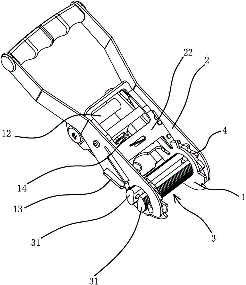
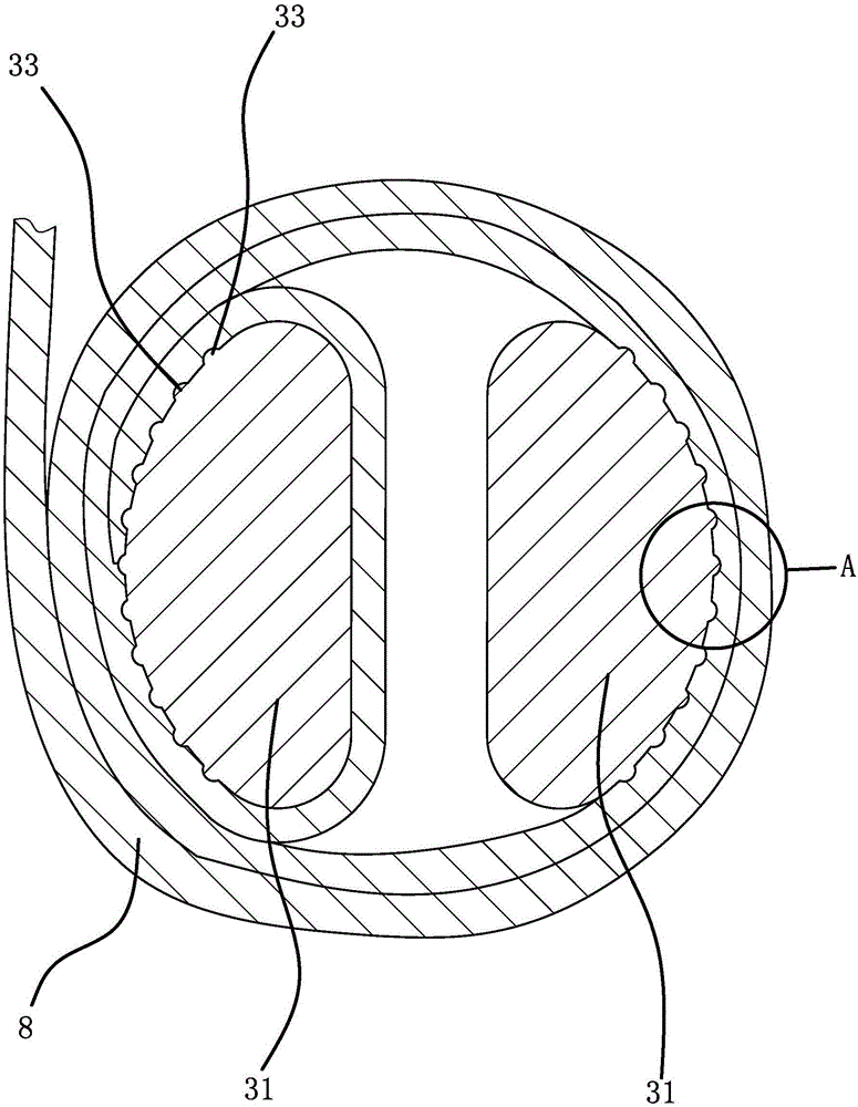
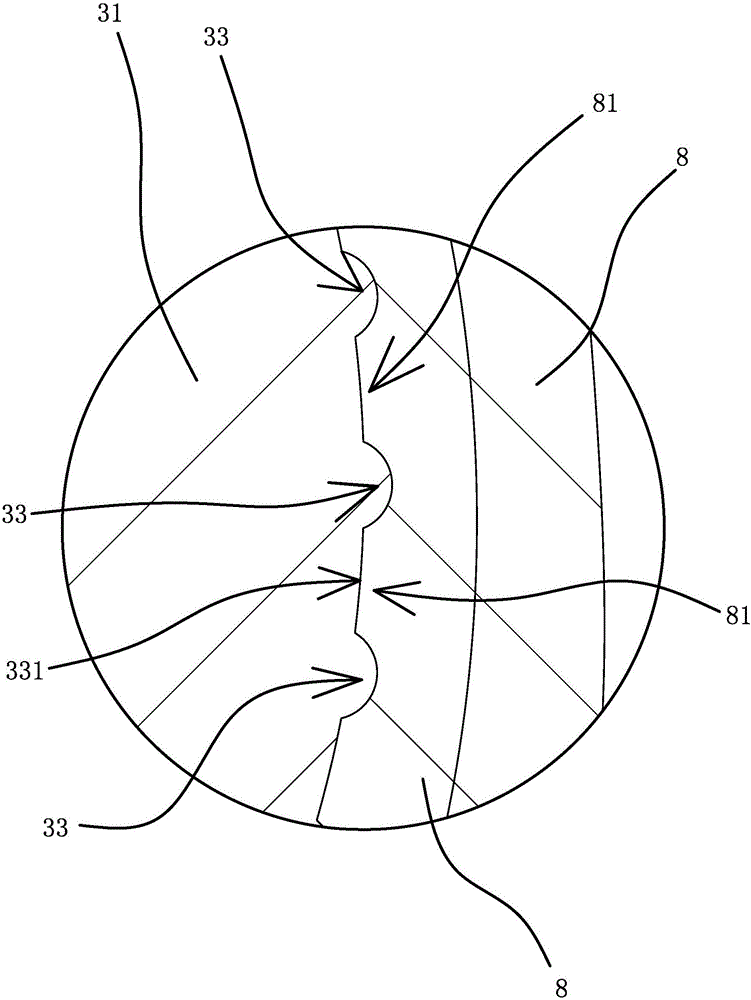
[0033] Such as figure 1 and figure 2 As shown, the binder includes a bracket 1, a handle 2 and a belt shaft 3. The belt shaft 3 includes two half-moon shafts 31, and there is a gap 32 between the two half-moon shafts 31 for the strap 8 to pass through. One end of the bracket 1 and the handle One end of 2 is pivotally connected by belt shaft 3, pivot hole 1 11 is opened on bracket 1, pivot hole 2 21 is opened on handle 2, two half-moon shafts 31 pass through pivot hole 1 1 and pivot hole 2 21 ; One end of the bracket 1 away from the belt shaft 3 is fixed with a fixed shaft 12, the belt shaft 3 is fixed with a ratchet 4, the ratchet 4 is located between the bracket 1 and the handle 2, and the middle part of the ratchet 4 has two half-moon holes, two half-moon holes The shafts 31 pass through the half-moon holes respectively. The handle 2 is provided with a push plate 22 that can be clamped to the ratchet 4 and can drive the ratchet 4 to rotate forward. The push plate 22 can sl...
Embodiment 2
[0037] The structure and principle of this embodiment are basically the same as that of Embodiment 1, the difference is that: Figure 7 As shown, the raised portion 33 includes several oblique ribs one 6 and several oblique ribs two 61, the sides of the oblique rib one 6 and the oblique rib two 61 are arc surfaces, and the adjacent oblique ribs one 6 The distances between them are all the same, the distances between adjacent oblique ribs 2 61 are all the same, and the distance between adjacent oblique ribs 6 is the same as the distance between adjacent oblique ribs 61 , the oblique convex rib one 6 and the oblique convex rib two 61 cross each other to form a network structure, and the adjacent oblique convex rib one 6 and the adjacent oblique convex rib two 61 form a pit 62, and the pit 62 is embedded Section 331. The strap 8 located in the innermost circle is embedded in the pit 62 under the pressure of the outer ring. The shape of the strap 8 embedded in the pit 62 matches ...
Embodiment 3
[0039] The structure and principle of this embodiment are basically the same as that of Embodiment 1, the difference is that: Figure 8 As shown, the raised portion 33 includes several hemispherical bumps 7, the bumps 7 are hemispherical, the bumps 7 are distributed at equal intervals along the length direction of the abutment surface 312, and the plurality of bumps 7 are distributed along the length of the abutment surface 312. The circular arc direction is distributed in an equal arc, and the embedded portion 331 is formed between adjacent bumps 7 . The strap 8 located in the innermost ring is embedded into the embedded part 331 between the convex points 7 under the action of the pressure of the outer ring. The shape of the strap 8 embedded in the embedded part 331 matches the shape of the embedded part 331. The belt 8 will abut against the corresponding convex point 7, and when the two half-moon shafts 31 rotate, the strap 8 embedded in the embedded part 331 will abut again...
PUM
 Abstract
Description
Claims
Application Information
 - R&D
- Intellectual Property
- Life Sciences
- Materials
- Tech Scout
- Unparalleled Data Quality
- Higher Quality Content
- 60% Fewer Hallucinations
Browse by: Latest US Patents, China's latest patents, Technical Efficacy Thesaurus, Application Domain, Technology Topic, Popular Technical Reports.
© 2025 PatSnap. All rights reserved.Legal|Privacy policy|Modern Slavery Act Transparency Statement|Sitemap|About US| Contact US: help@patsnap.com


