Rotary suction assembly

A component and suction cup technology, applied in the field of rotary suction components, can solve the problems of low labor efficiency and high cost, and achieve the effect of improving production efficiency

Inactive Publication Date: 2016-12-07
常州节卡智能装备有限公司
View PDF7 Cites 4 Cited by
  • Summary
  • Abstract
  • Description
  • Claims
  • Application Information

AI Technical Summary

Problems solved by technology

[0003] The technical problem to be solved by the present invention is: in order to solve the technical problems of low labor efficiency and high cost, the present invention provides a rotary suction assembly

Method used


Image

  • Rotary suction assembly
  • Rotary suction assembly
  • Rotary suction assembly

Examples


Embodiment Construction

[0019] The present invention is described in further detail now in conjunction with accompanying drawing. These drawings are all simplified schematic diagrams, which only illustrate the basic structure of the present invention in a schematic manner, so they only show the configurations related to the present invention.

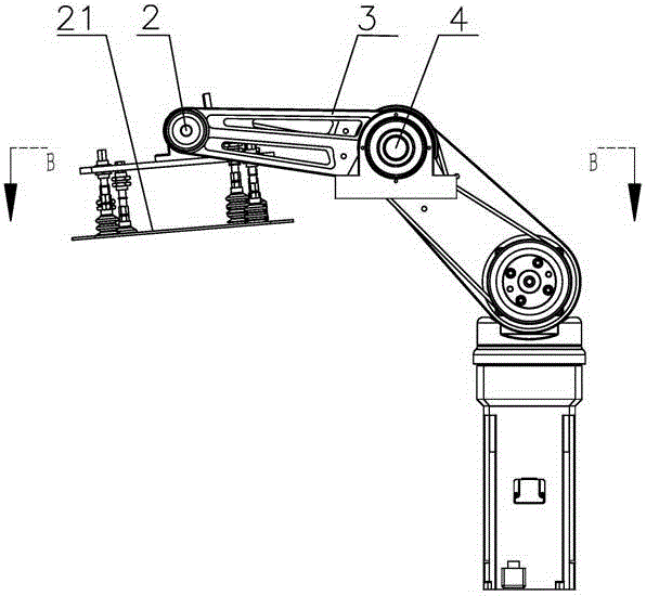
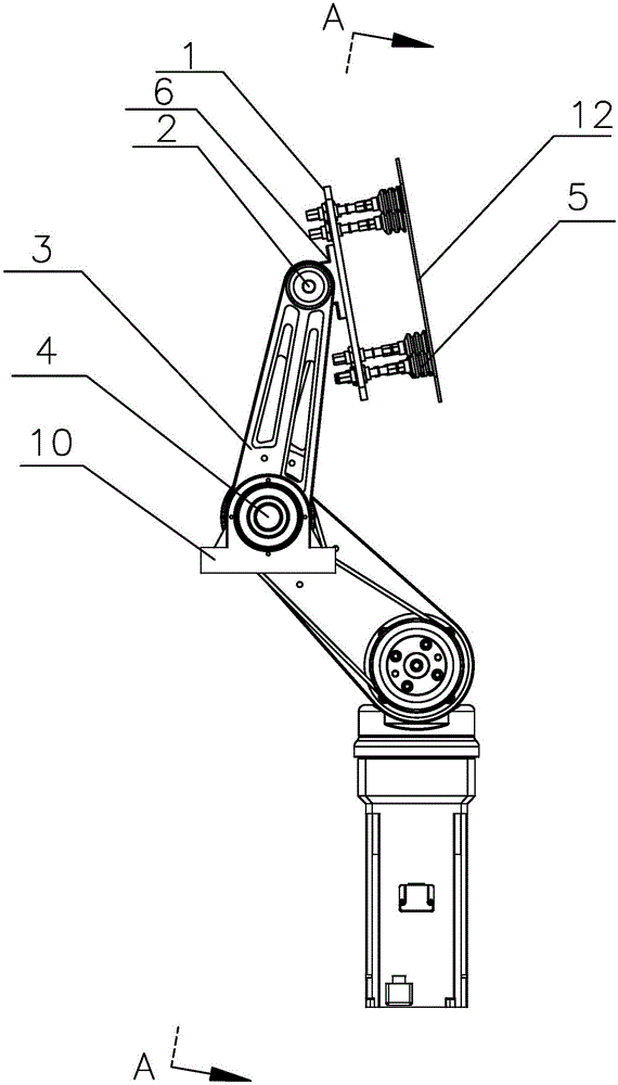
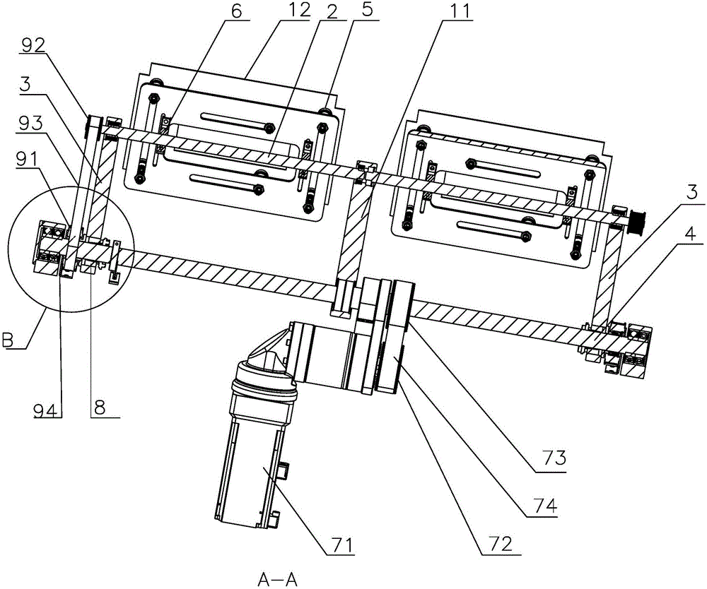
[0020] like Figure 1-3 Shown is the best embodiment of the present invention, a rotary suction assembly, including a suction cup plate 1, a rotating shaft 2, a swing arm 3 and a drive shaft 4, one side of the suction cup plate 1 is fixedly mounted with a suction cup 5, and the other side of the suction cup plate 1 A fixed bracket 6 is provided, the fixed bracket 6 is fixedly set on the rotating shaft 2, one end of the swing arm 3 is set on the rotating shaft 2, the other end of the swing arm 3 is set on the drive shaft 4, and the other end of the swing arm 3 is installed with a One end of the swing arm 3 is a swinging mechanism that swings around the axis of...


PUM


Abstract

The invention relates to the technical field of packaging devices, in particular to a rotary suction assembly. The rotary suction assembly comprises sucking disc plates, a rotating shaft, swinging arms and a driving shaft, wherein sucking discs are fixedly mounted on one sides of the sucking disc plates; fixed brackets are arranged on the other sides of the sucking disc plates; the fixed brackets are fixedly mounted on the rotating shaft in a sleeving manner; one ends of the swinging arms are mounted on the rotating shaft in a sleeving manner; the other ends of the swinging arms are mounted on the driving shaft in a sleeving manner; swinging mechanisms which can enable one ends of the swinging arms to perform circumferential swinging around the axis of the driving shaft are mounted at the other ends of the swinging arms; a synchronous belt transmission mechanism which can drive the rotating shaft to rotate is connected on the rotating shaft; and the swinging mechanisms and the synchronous belt transmission mechanism synchronously move. According to the rotary suction assembly, the rotating shaft can rotate on the own axis while the swinging arms swing, so that a vertically placed paperboard is taken to a low place from a high place; and the paperboard is overturned to be horizontally placed, the automatic production is achieved, and the production efficiency is improved.

Description

technical field [0001] The invention relates to the technical field of packaging equipment, in particular to a rotary suction assembly. Background technique [0002] The packaging of the dairy and beverage industries is gradually developing towards automation and intelligence. After the filling process is completed, the conveying mechanism transports the filled products to the packaging station. The packaging station needs to pack milk bags in a certain quantity. In the packaging box, cardboard needs to be put into the packaging box as a liner. The existing way of picking up cardboard is mostly manual or semi-automatic, which has low efficiency and is not suitable for high-efficiency automated production in large quantities. High labor costs increase the employment cost of enterprises, which is not conducive to reducing staff and increasing efficiency. Contents of the invention [0003] The technical problem to be solved by the present invention is: in order to solve the ...

Claims


Application Information

Patent Timeline
Patent Type & Authority Applications(China)
IPC IPC(8): B65B61/22B65H3/08B65H5/14
CPCB65B61/22B65H3/0883B65H5/14
Inventor 李明洋
Owner 常州节卡智能装备有限公司
Why Eureka
Try Eureka