Remote-control ultraviolet ray disinfection water box

A remote control and ultraviolet light technology, which is applied in the direction of light water/sewage treatment, water supply equipment, water saving, etc., can solve the problems of inability to remote control, increase the length of the pipeline, and inconvenience, so as to improve the sterilization effect and reduce the pipeline Length, the effect of improving the sterilization efficiency

Inactive Publication Date: 2016-12-07
SUZHOU COOBOS FLUID TECH
View PDF4 Cites 4 Cited by
  • Summary
  • Abstract
  • Description
  • Claims
  • Application Information

AI Technical Summary

Problems solved by technology

[0002] For secondary water supply, the traditional water tank is generally only used as an ordinary container with water storage function, with a single function
[0003] However, the existing water tanks are equipped with ultraviolet light disinfection. Usually, the ultraviolet light disinfection device is installed on the outside of the water tank in the form of a side pipe, which is separated from the water tank. Resistance, and the attachment of ultraviolet light tubes and other accessories in the bypass tube will also increase the water flow resistance. This disinfection method is to instantly kill bacteria that flow through tap water quickly, so high-power ultraviolet light tubes are required, and the cost is relatively high.
[0004] Moreover, after adding an ultraviolet light disinfection device to the existing water tank, the staff needs to stand on the ultraviolet light disinfection device for manipulation, and remote control cannot be performed, which is very inconvenient

Method used


Image

  • Remote-control ultraviolet ray disinfection water box

Examples


Embodiment

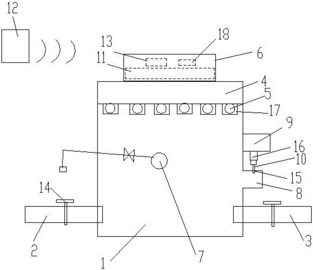
[0019] Embodiment: A remote-controlled ultraviolet light disinfection water tank, including a water tank body 1, the water tank body is provided with a water inlet pipe 2 and a water outlet pipe 3, the water tank body is open, and the top of the water tank body is fixed with a cover Plate 4, several ultraviolet light tubes 5 are installed on the lower end of the cover plate, a control box 6 is installed on the upper end of the cover plate, a float valve 7 is installed in the water tank body, and the side wall of the water tank body is provided with There is an overflow tank 8, and the overflow tank is connected with the water tank body, and a water quality detector 9 is installed above the overflow tank, and the detection head 10 of the water quality detector is telescopically inserted in the overflow tank up and down. The ultraviolet light tube, the water quality detector and the float valve are all communicated with the control box;

[0020] Also comprise wireless signal tra...


PUM


Abstract

The invention discloses a remote-control ultraviolet ray disinfection water box. The remote-control ultraviolet ray disinfection water box comprises a water box body, wherein a water inlet pipe and a water outlet pipe are arranged on the water box body; the water box body is opened, and a cover plate is fixed at the top of the water box body; a plurality of ultraviolet ray lamp pipes are mounted at the lower end of the cover plate, a control box is mounted at the upper end of the cover plate, and a float valve is mounted in the water box body; a water spilling groove is formed in the side wall of the water box body, and communicates with the water box body; a water quality testing meter is mounted above the water spilling groove, and a detection head of the water quality testing meter is arranged in the water spilling groove in an up-and-down telescopic inserting manner; the ultraviolet ray lamp pipes, the water quality testing meter and the float valve are all in communication connection with the control box; and the remote-control ultraviolet ray disinfection water box also comprises a wireless signal transmitter, a wireless signal receiver and a signal converter are mounted in the control box, the wireless signal transmitter and the wireless signal receiver are connected through a wireless network, and the wireless signal receiver transmits signals to the signal converter, so that wireless remote control can be performed, the length of a pipeline is reduced, the flow resistance is reduced, and the cost is reduced.

Description

technical field [0001] The invention relates to a water tank, in particular to a remote-controlled ultraviolet light disinfection water tank. Background technique [0002] For secondary water supply, the traditional water tank is generally only used as an ordinary container with water storage function, and has a single function. If you need to add ultraviolet light disinfection, you generally need to add a special ultraviolet light sterilizer. [0003] However, the existing water tanks are equipped with ultraviolet light disinfection. Usually, the ultraviolet light disinfection device is installed on the outside of the water tank in the form of a side pipe, which is separated from the water tank. Resistance, and the attachment of ultraviolet lamps and other accessories in the bypass pipe will also increase the water flow resistance. This disinfection method is to instantly kill bacteria flowing through tap water, so high-power ultraviolet lamps are required, and the cost is...

Claims


Application Information

Patent Timeline
Patent Type & Authority Applications(China)
IPC IPC(8): C02F1/32E03B11/02E03B7/07
CPCC02F1/32C02F2201/3227E03B7/074E03B11/02Y02A20/00
Inventor 朱洪斌周晓斌
Owner SUZHOU COOBOS FLUID TECH
Why Eureka
Try Eureka