Aerobic three-phase separator and method for applying aerobic three-phase separator to treating sewage

A three-phase separator, sewage technology, applied in biological water/sewage treatment, water/sludge/sewage treatment, chemical instruments and methods, etc., can solve problems such as unfavorable biodegradation reaction, reduction of biological activity, energy consumption, etc. Achieve the effect of improving processing efficiency, reducing floor space, reducing investment and operating costs

Inactive Publication Date: 2016-12-07
SHENZHEN QINGYAN ENVIRONMENTAL TECH CO LTD
View PDF6 Cites 6 Cited by
  • Summary
  • Abstract
  • Description
  • Claims
  • Application Information

AI Technical Summary

Problems solved by technology

During this process, the activated sludge will continue to circulate between the aerobic and sedimentation tanks. On the one hand, it consumes a lot of energy. On the other hand, due to the continuous change of the microbial growth environment, its biological activity is reduced, which is not conducive to the biodegradation reaction. carry out

Method used


Image

  • Aerobic three-phase separator and method for applying aerobic three-phase separator to treating sewage
  • Aerobic three-phase separator and method for applying aerobic three-phase separator to treating sewage
  • Aerobic three-phase separator and method for applying aerobic three-phase separator to treating sewage

Examples


Embodiment Construction

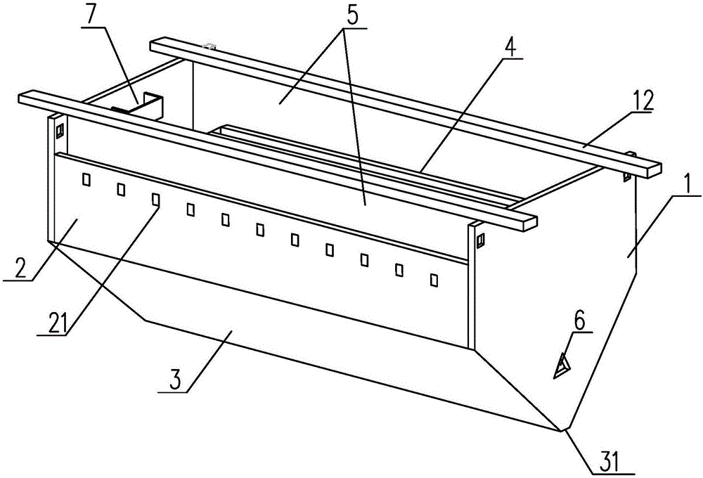
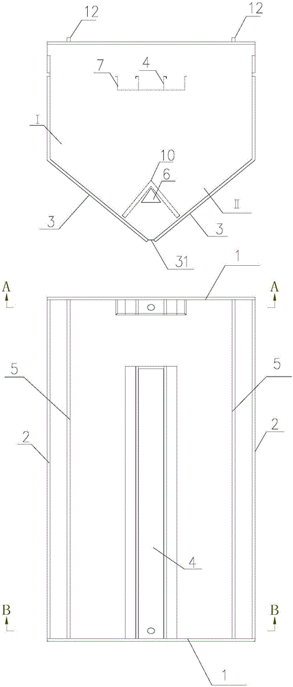
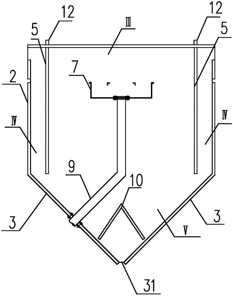
[0028] In order to make the object, technical solution and advantages of the present invention clearer, the present invention will be further described in detail below in conjunction with the accompanying drawings and embodiments. It should be understood that the specific embodiments described here are only used to explain the present invention, not to limit the present invention.

[0029] It should be noted that when an element is referred to as being “fixed on” or “disposed on” another element, it may be directly on the other element or there may be an intervening element at the same time. When an element is referred to as being "connected to" another element, it can be directly connected to the other element or intervening elements may also be present.

[0030] It should also be noted that the orientation terms such as left, right, up, and down in the embodiments of the present invention are only relative concepts or refer to the normal use state of the product, and should ...


PUM

PropertyMeasurementUnit
angleaaaaaaaaaa

Abstract

The invention relates to an aerobic three-phase separator which comprises two end plates, flow guide plates and oblique plates. The two end plates are parallelly arranged, and comprise bottom inverted-trapezoidal plates and top rectangular plates which are integrally formed, each flow guide plate is perpendicularly connected with two corresponding side edges of the two end plates, a rectangular cavity is arranged on the tops of the flow guide plates, the bottom of each flow guide plate is inwardly folded and is perpendicularly connected with two corresponding side edges of the bottom inverted-trapezoidal plates of the end plates to form the corresponding oblique plates, and the oblique plates are provided with a sludge backflow seam and a bottom conical cavity. The aerobic three-phase separator is characterized by further comprising an overflow weir, a drain pipe, settling partition plates, a sludge settling zone, flow guide zones and a conical sludge hopper; the overflow weir is positioned between the two end plates on the horizontal axis of the top rectangular cavity, the drain pipe is arranged between the bottom of the overflow weir and the oblique plates, the settling partition plates which respectively downwardly overhang along the tops of the two end plates are symmetrically arranged between the overflow weir and the flow guide plates on two sides of the overflow weir, the sludge settling zone is formed between the settling partition plates, the flow guide zones are formed between the settling partition plates and the flow guide plates, the conical sludge hopper is enclosed by the oblique plates and the two end plates, and a plurality of first through holes are formed in the side surfaces of the flow guide plates.

Description

technical field [0001] The invention relates to a separation and precipitation device, in particular to a gas, liquid and solid three-phase separator used in an aerobic biological treatment process. Background technique [0002] The aerobic activated sludge method is a relatively mature biological treatment technology, which is widely used in the current urban sewage treatment. In the treatment of some high-concentration industrial wastewater, the anaerobic sewage must also pass through the aerobic activated sludge. method for processing. The factors that play a key role in the treatment effect in the aerobic activated sludge sewage treatment system are mainly sludge concentration (amount of microorganisms), dissolved oxygen efficiency (microbial activity) and sedimentation efficiency (mud-water separation effect), that is, good The sewage treatment system of the oxygen active substance method will involve the contact and separation of gas, liquid and solid three-phase, and...

Claims


Application Information

Patent Timeline
Patent Type & Authority Applications(China)
IPC IPC(8): C02F3/12
CPCC02F3/1221Y02W10/10
Inventor 刘旭刘淑杰陈福明
Owner SHENZHEN QINGYAN ENVIRONMENTAL TECH CO LTD
Why Eureka
Try Eureka