

Device and method for treating high-salinity sewage
A sewage treatment device, high salinity technology, applied in biological water/sewage treatment, water/sewage multi-stage treatment, water/sludge/sewage treatment, etc. The effect of promoting nitrification and improving the efficiency of sewage treatment
- Summary
- Abstract
- Description
- Claims
- Application Information
AI Technical Summary
Problems solved by technology
Method used
Image

Examples
Embodiment Construction
[0030] In order to make the object, technical solution and advantages of the present invention clearer, the present invention will be further described in detail below in conjunction with the accompanying drawings and embodiments. It should be understood that the specific embodiments described here are only used to explain the present invention, not to limit the present invention.
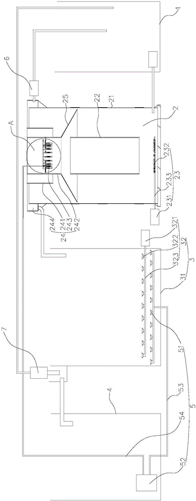
[0031] see Figure 1~3 , the embodiment of the present invention provides a high-salinity sewage treatment device, comprising a regulating tank 1, a vertical three-phase fluidized bed 2, a biological aerated filter tank 3 and an intermediate pool 4 connected in sequence; wherein, the vertical three-phase Phase fluidized bed 2 includes:
[0032] A vertically arranged reaction cylinder 21, wherein a reaction chamber is formed in the reaction cylinder 21;
[0033] A guide tube 22 coaxially built into the reaction chamber;
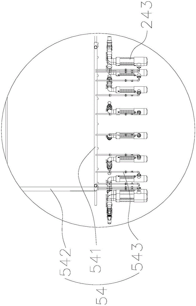
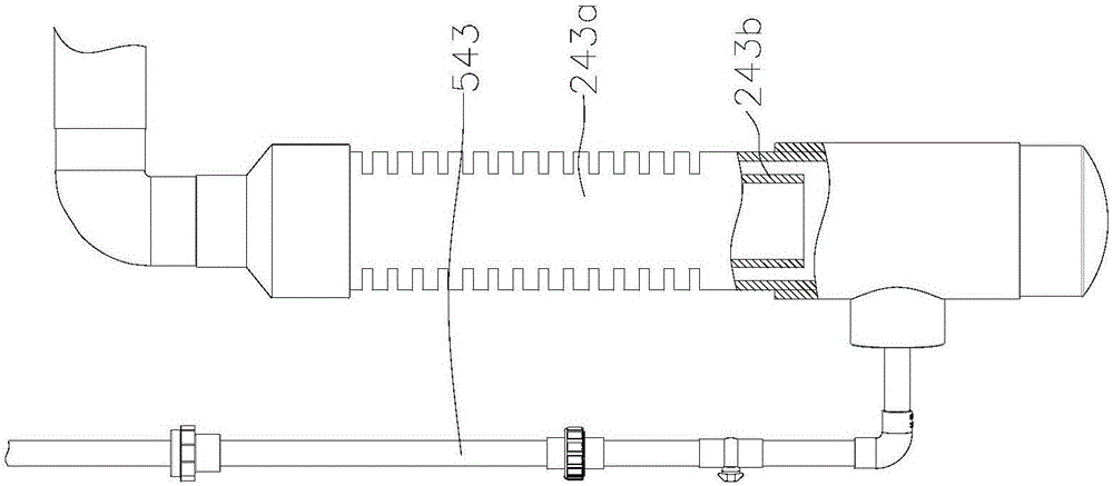
[0034] The first aeration mechanism 23 includes a first aeration fan 231, a...
PUM
 Abstract
Description
Claims
Application Information