
Magnetic separation device facilitating separation of sundries in sewage

A magnetic separation device and technology for sundries, applied in the fields of magnetic field/electric field water/sewage treatment, etc., can solve the problem of increased treatment costs, inability to flocculate pollutants and magnetic seed treatment and recovery, and inability to ensure adequate mixing of magnetic adsorbents and magnetic field distribution. and other problems, to achieve the effect of promoting separation effect and high efficiency of sewage treatment

Active Publication Date: 2019-06-21
JIANGSU ZHAOSHENG ENVIRONMENTAL PROTECTION TECH CO LTD
View PDF21 Cites 2 Cited by
  • Summary
  • Abstract
  • Description
  • Claims
  • Application Information

AI Technical Summary

Problems solved by technology

However, this device has the following disadvantages: when performing magnetic separation, it cannot ensure that the magnetic adsorbent is fully mixed in the sewage and the magnetic field is unevenly distributed, and when cleaning the flocculated pollutants, it cannot effectively remove the flocculated pollutants and magnetic species. Recycling by chemical treatment leads to poor flocculation effect, increased treatment cost, and waste of resources

Method used


Image

  • Magnetic separation device facilitating separation of sundries in sewage
  • Magnetic separation device facilitating separation of sundries in sewage
  • Magnetic separation device facilitating separation of sundries in sewage

Examples


Embodiment

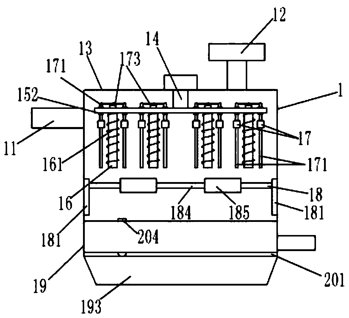
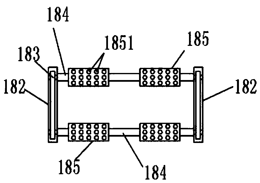
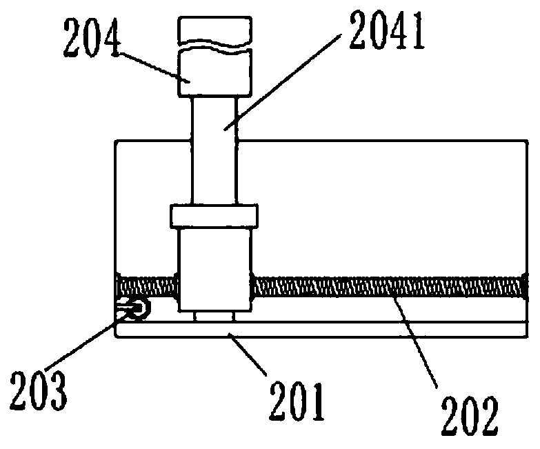
[0022] Such as figure 1 , 6 As shown, a magnetic separation device for facilitating the separation of sewage and debris mainly includes a separation chamber 1, a power supply device and a control device. The separation chamber 1 is provided with a water inlet 11, the upper end of the separation chamber 1 is provided with a feed channel 12, and the separation chamber 1 Including reaction frame 13, rotating shaft 14, fixed plate 15, iron core rod 16, separator 17, mixer 18, collection tank 19, rotating shaft 14 is arranged at the top of reaction frame 13, rotating shaft 14 is connected to rotating motor 1. The fixed plate 15 is arranged on the rotating shaft 14. The fixed plate 15 is provided with annular slides 151. There are four annular slides 151, which are equally spaced on the fixed plate 15. Each of the four annular slides 151 is provided with Two movable sleeves 152, and the two movable sleeves 152 in each annular slide 151 are arranged symmetrically. There are four iron c...

experiment example 1

[0031] Experimental example 1: Before water intake: COD 250-300mg / L, turbidity (NTU) 180-200, ammonia nitrogen content 60-70mg / L, TP15-20mg / L;

experiment example 2

[0032] Experimental example 2: Before water intake: COD 350-410mg / L, turbidity (NTU) 240-290, ammonia nitrogen content 80-90mg / L, TP20-23mg / L;


PUM


Abstract

The invention provides a magnetic separation device facilitating separation of sundries in sewage. The magnetic separation device mainly comprises a separating cavity, a power supply device and a control device, wherein the separating cavity comprises a reaction frame body, a rotating shaft, a fixed plate, iron mandrels, separators, a mixer and a collecting tank; annular slides are formed on the fixed plate; the four iron mandrels are arranged in the centers of the four annular slides respectively; the separators are in sliding connection with the annular slides through movable sleeves; each separator comprises a guide rod, an air blowing device and a fixed rod, and the guide rod is arranged on the corresponding movable sleeve in a penetrating manner; the mixer is located below the separators, and electric telescopic rods are arranged at the left end and the right end of the mixer; the collecting tank is of an inverted trapezoidal structure and located below the mixer, a boss is arranged in the horizontal middle of the collecting tank, a mud scraping device is arranged in the boss in a penetrating manner, and a collecting box is arranged below the collecting tank. The magnetic separation device is reasonable in structure and good in flocculation effect, floccular pollutants and magnetic seeds are effectively treated and recovered, and the treatment cost is reduced.

Description

Technical field [0001] The invention belongs to the technical field of water treatment, and specifically relates to a magnetic separation device that is convenient for separating sewage impurities. Background technique [0002] In processes such as sewage treatment and purification, the effect of magnetic fields on water, other solvents and dissolved oxygen can be used to directly degrade organic matter. The magnetic effect can promote the dissolution of oxygen in water and may generate active oxygen in the water. These active oxygen groups have strong oxidizing properties and can oxidize organic matter in water, thereby reducing the content of organic matter in the water. Moreover, the magnetic field generated by the rotating magnet bar can play a certain stirring effect, and the organic particles can adhere to the magnetic flocculant, so that the contaminants adsorbed on the magnetic powder can be magnetically aggregated and flocculated and accelerate the sedimentation. The m...

Claims


Application Information

Patent Timeline
IPC IPC(8): C02F1/48
Inventor 周震球何俊荣杰
Owner JIANGSU ZHAOSHENG ENVIRONMENTAL PROTECTION TECH CO LTD
Learn More