
Glass transferring system for glass bending furnace

A glass transfer and hot bending furnace technology, applied in the field of heat treatment, can solve the problems of automatic reversing transmission of glass plates, easy downward bending of the conveyor belt, and unstable placement of glass plates, etc., achieving low cost, reduced space occupation, and automation high degree of effect

Inactive Publication Date: 2016-12-07
浙江宇清热工科技股份有限公司
View PDF5 Cites 1 Cited by
  • Summary
  • Abstract
  • Description
  • Claims
  • Application Information

AI Technical Summary

Problems solved by technology

[0004] Although the above technical solution lifts the glass plate through the lifting platform assembly and the crank assembly, and solves the problem of glass plate lifting, there are still some shortcomings: the technical solution uses the conveyor belt to complete the conveying of the glass by assembling the conveyor belt between the pulleys. However, because the conveyor belt is relatively soft, the conveyor belt is easy to bend downward when the large-size glass plate is placed on the conveyor belt, and the fatigue strength is high, resulting in unstable placement of the glass plate, affecting the transmission speed, and the glass is easy to break. At the same time, the mechanism only has one-way Transmission, unable to realize automatic reversing transmission of the glass plate, the scope of application is small

Method used


Image

  • Glass transferring system for glass bending furnace
  • Glass transferring system for glass bending furnace
  • Glass transferring system for glass bending furnace

Examples


Embodiment 1

[0041] The embodiments are described below with reference to the accompanying drawings. The embodiments shown below do not limit the invention content described in the claims. required for the solution.

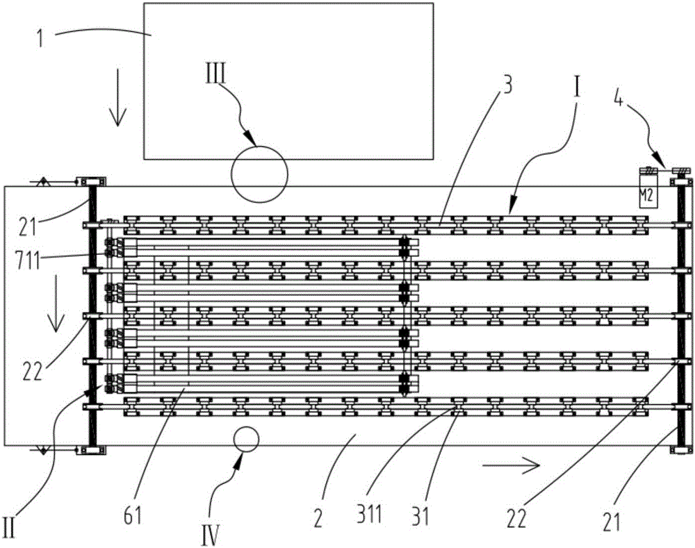
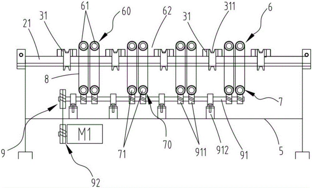
[0042] figure 1 It is a schematic diagram of a preferred embodiment of a glass transfer system for a glass bending furnace according to the present invention, and the transfer system includes:

[0043] Vertical conveying mechanism I, used to receive the glass 1 conveyed from the glass bending furnace and convey the glass 1 along the original path;

[0044] Horizontal conveying mechanism II is used to receive the glass 1 conveyed from the longitudinal conveying mechanism I and convey the glass 1 along the direction perpendicular to the original path to the next process for processing;

[0045] The first detection module III is used to detect the moving distance of the glass 1 transported from the glass 1 bending furnace, and the longitudinal transmission mechanism I starts t...


PUM


Abstract

The invention relates to a glass transferring system for a glass bending furnace. The glass transferring system comprises a longitudinal delivery mechanism, a horizontal delivery mechanism, a first detection die set and a second detection die set, wherein the longitudinal delivery mechanism is used for receiving glass transported from the glass bending furnace and transporting the glass along an original path; the horizontal delivery mechanism is used for receiving the glass transported from the longitudinal delivery mechanism and transporting the glass to a next working procedure in the direction perpendicular to the original path; the first detection die set is used for detecting the moving distance of the glass transported from the glass bending furnace, and when the glass reaches to a first pre-set position, the longitudinal delivery mechanism begins to transport the glass; and the second detection die set is used for detecting the moving distance of the glass transported from the longitudinal delivery mechanism, and when the glass reaches to a second pre-set position, the horizontal delivery mechanism begins to transport the glass. According to the glass transferring system disclosed by the invention, the horizontal delivery mechanism and the longitudinal delivery mechanism are skillfully combined, so that the automatic reversing delivery of the glass is realized, besides, the glass is quickly, accurately and continuously transported in different delivery directions, the automation degree is high, and the operation is stable.

Description

technical field [0001] The invention relates to the technical field of heat treatment, in particular to a glass transfer system for a glass bending furnace. Background technique [0002] The glass processed by the glass hot bending furnace usually needs to be lowered or raised to the transportation line of different heights for the next process processing. In this process, the transfer of the glass needs to be realized by the conveying mechanism. The glass is in the actual conveying process. , is often transported from the previous processing equipment to the next processing equipment, and its moving direction is changed by 90° or 180° to meet the processing requirements. Recently, the traditional transfer and transportation methods mostly use manipulator handling or chain transmission. As we all know, glass is fragile, especially for large-size glass transportation. Shaking, easy to fall off or break, and the chain transmission can only realize the same direction of transm...

Claims


Application Information

Patent Timeline
Patent Type & Authority Applications(China)
IPC IPC(8): C03B35/00
CPCC03B35/00
Inventor 吴俊涵陈剑波吴俊杰余鹏飞
Owner 浙江宇清热工科技股份有限公司
Learn More