A double-cone refiner with internal flow guide channels

A diversion channel, double cone technology, applied in the field of papermaking, can solve the problems of large feeding resistance, reduced slurry, and inability to effectively improve refining efficiency, and achieves the goal of improving work efficiency, refining efficiency, and throughput. Effect

Inactive Publication Date: 2018-01-23
TIANJIN UNIV OF SCI & TECH
View PDF9 Cites 0 Cited by
  • Summary
  • Abstract
  • Description
  • Claims
  • Application Information

AI Technical Summary

Problems solved by technology

Generally, the feeding pressure of the refiner is constant, and the gap flow refining method is when the gap between the grinding discs is small (0.15 ~ 0.3mm, this kind of grinding disc gap often occurs during beating, second-stage or third-stage refining), the feed The resistance is very large, and the slurry entering the refining area is obviously reduced, obviously the refining efficiency cannot be effectively improved
In addition, when the general conical refiner is fed at the small end, the cross-sectional area of ​​the refining area is small, and the slurry entering the refining area is limited. During the refining process, the cross-sectional area of ​​the refining area gradually increases. limited, so in the middle of the conical rotor, especially the big end, the efficiency of refining cannot be fully exerted

Method used


Image

  • A double-cone refiner with internal flow guide channels
  • A double-cone refiner with internal flow guide channels
  • A double-cone refiner with internal flow guide channels

Examples


Embodiment Construction

[0043] The present invention will be further described in detail below through the specific examples, the following examples are only descriptive, not restrictive, and cannot limit the protection scope of the present invention with this.

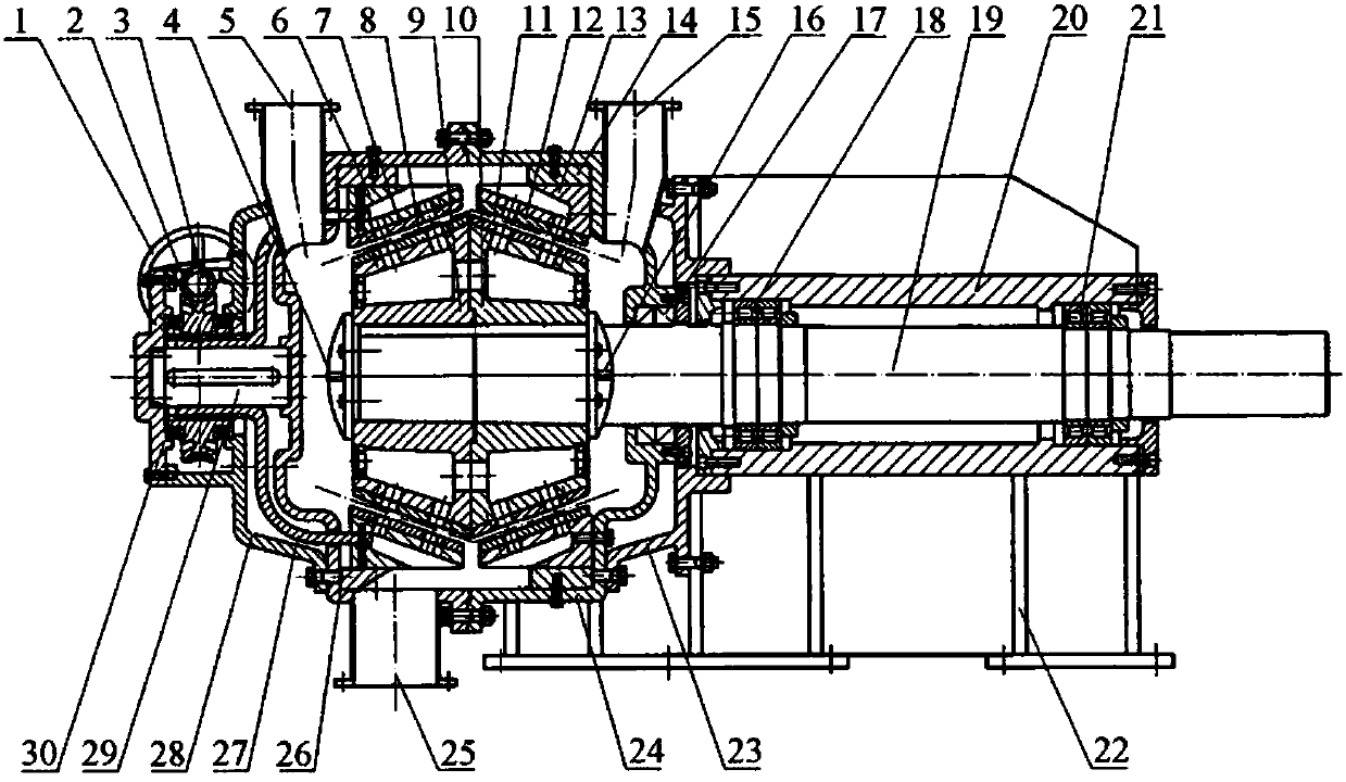
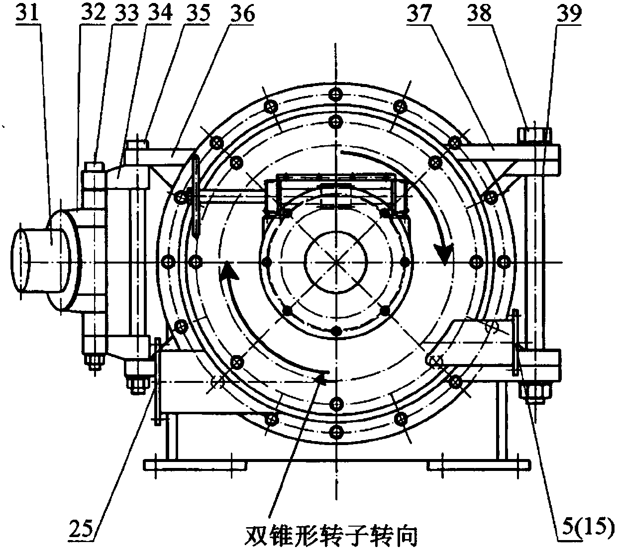
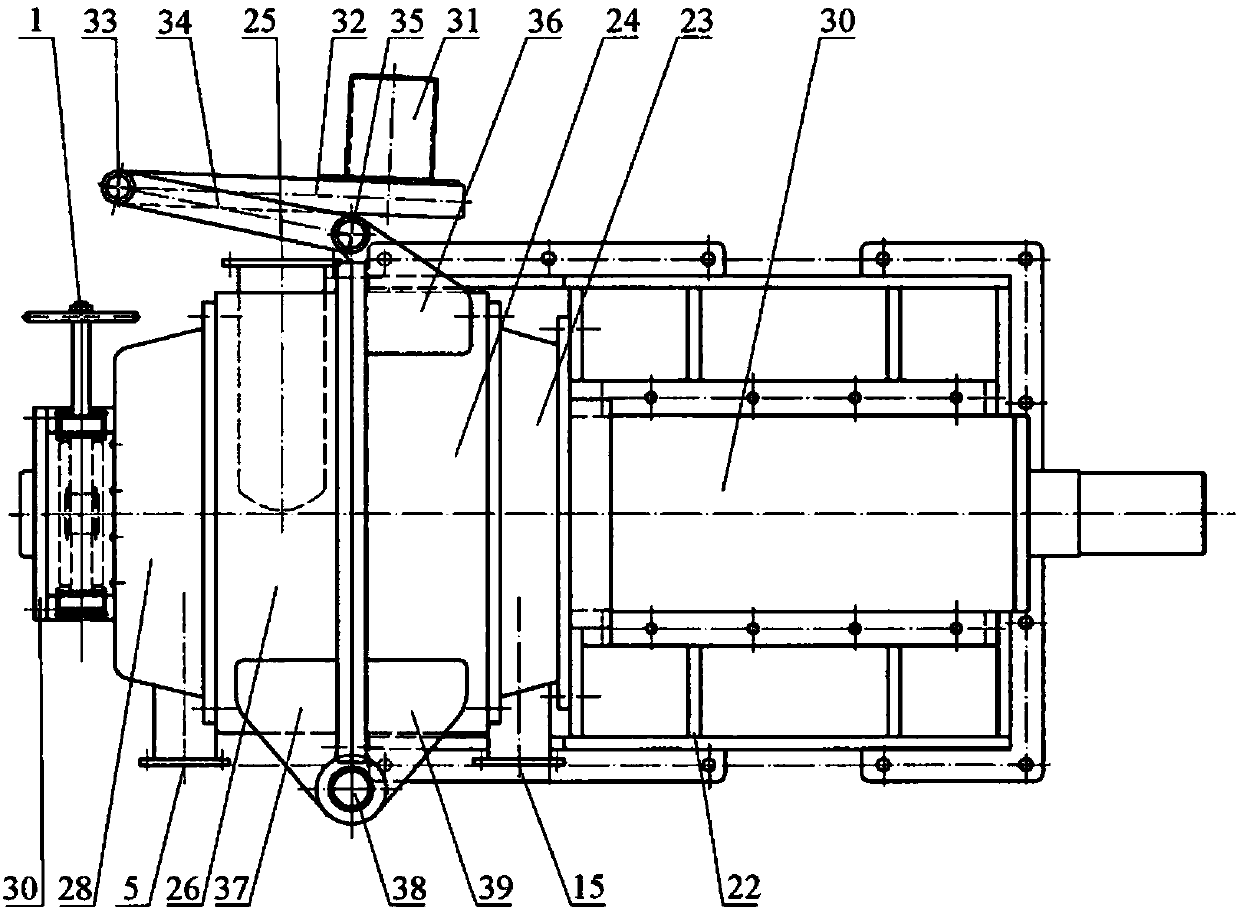
[0044] Such as Figure 1-3 As shown in , a double-cone refiner with an internal diversion channel includes a machine base 22, a grinding chamber seat 24, a grinding chamber cover 26, a bearing seat 20, a main shaft 19, a grinding disc gap adjustment mechanism, a double-cone The rotor, the double-cone stator, and the machine base are fixed with the grinding chamber seat and the bearing seat. The mill chamber seat and the machine base are connected through the mill chamber connection plate 23. The front and rear ends of the bearing seat are respectively equipped with a front bearing group 18 and a rear bearing group. 21. A double-cone stator and a double-cone rotor are installed in the grinding chamber seat. The outer ends of the two sides of ...


PUM

PropertyMeasurementUnit
pore sizeaaaaaaaaaa
angleaaaaaaaaaa

Abstract

The invention relates to a biconical refiner with an internal diversion channel. The biconical refiner comprises an engine base, a grinding chamber base, a main shaft, a biconical rotor and a biconical stator; the interior of a left conical rotor body and the interior of a right conical rotor body are each provided with a rotor diversion cavity, the rotor diversion cavities are communicated with a grinding chamber cover and a grinding chamber feeding cavity, and the external conical surface of the left conical rotor body and the external conical surface of the right conical rotor body are each provided with a rotor diversion hole perpendicular to the direction of the grinding surface; the interior of a left conical stator body and the interior of a right conical stator body are each provided with a stator diversion cavity, the stator diversion cavities are communicated with a grinding chamber cover discharge cavity, the external conical surface of the left conical stator body and the external conical surface of the right conical stator body are each provided with a stator diversion hole perpendicular to the direction of the refining surface, the rotor diversion cavities, the rotor diversion holes, the stator diversion holes and the stator diversion cavities from the internal diversion channel. According to the biconical refiner with the internal diversion channel, channel design is scientific and reasonable, throughput of the biconical refiner in unit time is increased, the refining efficiency of the middle and the big end of the conical rotor is exerted, and refining power consumption is further reduced.

Description

technical field [0001] The invention belongs to the field of papermaking, and relates to low-consistency, medium-consistency pulp refining or beating mechanical equipment, in particular to a double-cone pulp refiner with internal diversion channels. Background technique [0002] Refining and beating machinery is the key equipment of pulp and paper making enterprises, and it is also the mechanical equipment with high energy consumption. Since the working principles of pulping and beating machines are basically the same, but the adjustment requirements of working parameters are different, so this type of equipment can be collectively referred to as a refiner, and a refiner specially used for beating is also called a beater. [0003] Compared with the disk refiner, the conical refiner is a commonly used refiner because of its convenient gap adjustment and better refining quality. Conical refiners can be divided into single-cone refiners, double-cone refiners and triple-cone re...

Claims


Application Information

Patent Timeline
Patent Type & Authority Patents(China)
IPC IPC(8): D21D1/22
CPCD21D1/22
Inventor 王平沈晓阳
Owner TIANJIN UNIV OF SCI & TECH
Why Eureka
Try Eureka