An energy-saving and leak-proof curtain wall system

A curtain wall and leak-proof technology, applied to walls, buildings, building components, etc., can solve the problems of unfavorable application and development, insufficient installation precision, low construction efficiency, etc., and achieve the effect of convenient and convenient construction, less processing amount and rapid installation

Active Publication Date: 2018-10-02
ZHEJIANG CENT SOUTH CONSTR GROUP
View PDF4 Cites 0 Cited by
  • Summary
  • Abstract
  • Description
  • Claims
  • Application Information

AI Technical Summary

Problems solved by technology

[0002] Exposed frame curtain wall is the most traditional form of glass curtain wall and is the most widely used, but there are still many technical problems in the existing curtain wall system, such as insufficient installation accuracy, easy water seepage, low safety, low construction efficiency, etc., which are very unfavorable for future application and development

Method used


Image

  • An energy-saving and leak-proof curtain wall system
  • An energy-saving and leak-proof curtain wall system
  • An energy-saving and leak-proof curtain wall system

Examples


Embodiment 1

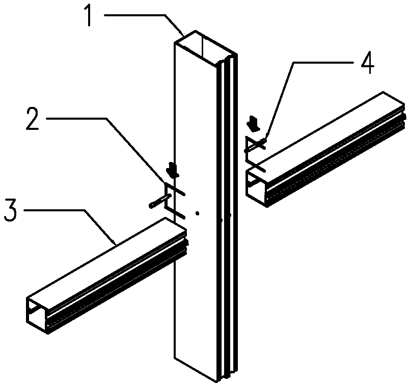
[0041] Embodiment 1. The column adapter part 18 and the beam adapter part 20 of the connector are arranged in a straight line, and are used to install the column 1 and the beam 3 whose connection surfaces are on the same horizontal plane.

Embodiment 2

[0042] Embodiment 2. A transition surface 57 is provided between the column adapter part 18 and the beam adapter part 20 of the connector, and the connector 5 with the transition surface 57 is formed into a stepped shape. The transition surface is used to connect the column 1 The fitting part is located in front of the crossbeam fitting part 20 and is suitable for being installed on the connection surface where the column protrudes from the crossbeam 2 .

Embodiment 3

[0043] Embodiment 3: A transition surface 57 is provided between the column adapter part 18 and the beam adapter part 20 of the connector, and the transition surface 57 of the connector 5 is used to position the column adapter part behind the beam adapter part; It is suitable for installation on the connection surface where the column 1 is recessed in the beam 3.

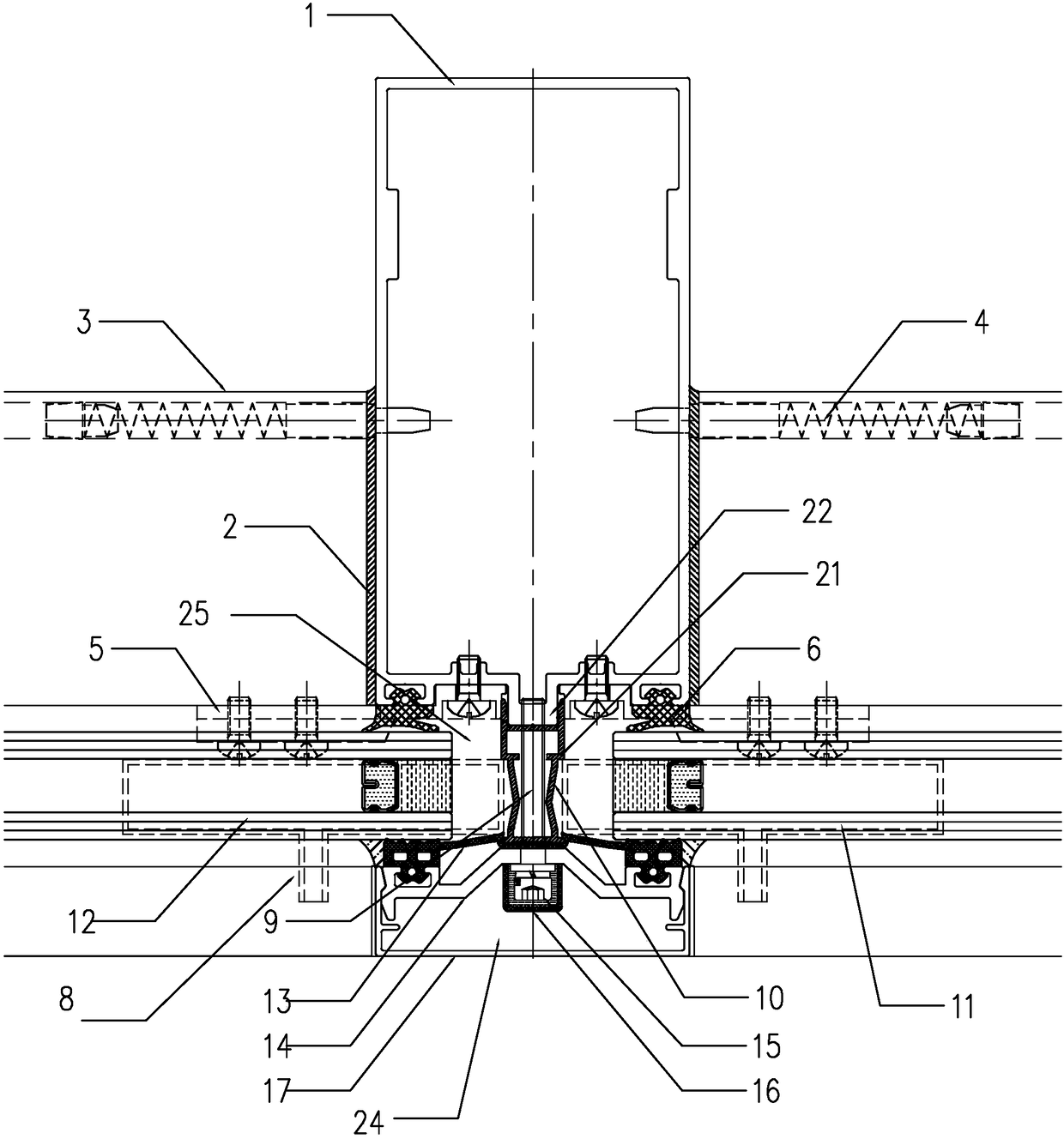
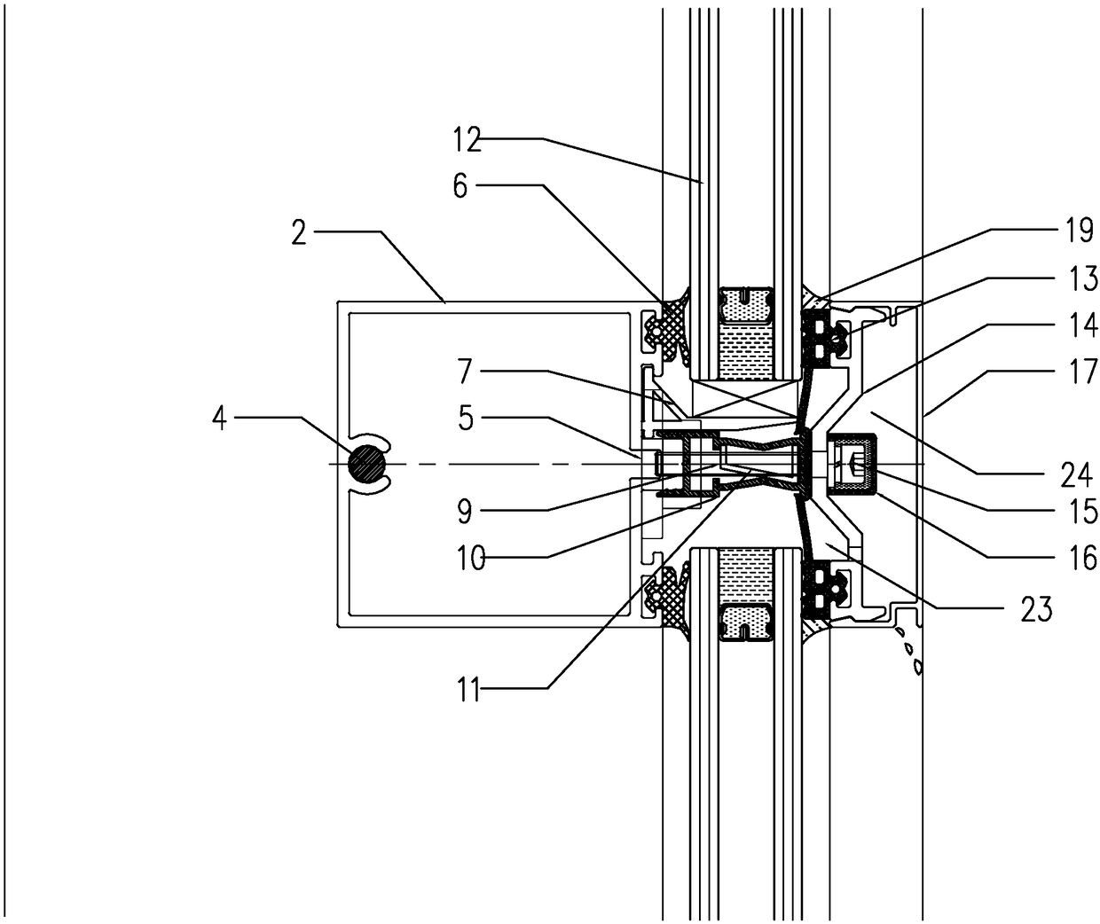
[0044] The outdoor rubber strip 13 is integrated, and two ends of the outdoor rubber strip 13 are respectively connected to adjacent glass plates 12 . The outdoor rubber strip 13 and the inner side of the pressure plate 14 form a leak-proof partition cavity 23 , and a bayonet is provided at the connection between the integral rubber strip and the heat insulation frame 10 .

[0045]The heat insulation frame 10 includes a strip heat insulation strip and a water collection tank 11 , and the heat insulation frame 10 at the seam of the glass plates 12 directly in front of the beam 3 is provided with the water collection ...


PUM


Abstract

The invention provides an energy-saving anti-leakage curtain wall system. The system comprises an anti-leakage structure and a connection structure. A drainage cavity in a buckle lid is a first-stage anti-leakage mechanism, a water collecting tank is used for making a heat-insulation cavity be communicated with the drainage cavity to form a drainage channel, and a heat-insulation frame is a second-stage anti-leakage mechanism. The connection structure comprises spring plug-pins and connecting pieces, and cross beams are connected with a vertical column through the spring plug-pins. Each connecting piece comprises a vertical column matching part and a cross beam matching part, wherein the vertical column matching part and the cross beam matching part are installed on the front side of the cross beam and the vertical column which are adjacent to each other and fixed. A waterproof structure includes multi-stage waterproof measures, the process is simple, and installation is quick. According to the rain curtain principle, capillary water leaks in a room. All components are conventionally machined and can be machined in a factory, so the components can be positioned and installed only by being aligned to bolt holes, and construction is more convenient. The connecting pieces can be matched with the cross beams and a notch or the front end of the vertical column at the same time, the machining amount is small, and environment protection and energy conservation are achieved.

Description

technical field [0001] The invention relates to a curtain wall system, in particular to an exposed frame glass curtain wall system. Background technique [0002] Exposed frame curtain wall is the most traditional form of glass curtain wall and is the most widely used, but there are still many technical problems in the existing curtain wall system, such as insufficient installation accuracy, easy water seepage, low safety, low construction efficiency, etc., which are very unfavorable for future application and development . Contents of the invention [0003] The technical problem to be solved by the present invention is to provide an anti-leakage and high-safety glass curtain wall anti-leakage structure. For this reason, the present invention provides the following technical solutions: [0004] An energy-saving and anti-leakage curtain wall system, including a column, a beam and a pressing plate, the pressing plate fixes the glass plate on the column, the system includes a...

Claims


Application Information

Patent Timeline
Patent Type & Authority Patents(China)
IPC IPC(8): E04B2/96
CPCE04B2/96
Inventor 王旭华
Owner ZHEJIANG CENT SOUTH CONSTR GROUP
Why Eureka
Try Eureka