Waste gas treatment structure applied to incineration unit

A waste gas treatment and incineration device technology, which is applied in the direction of climate sustainability, combustion technology mitigation, dry gas arrangement, etc., can solve problems affecting technology popularization and application, complex installation and maintenance, large space, etc., to improve heat exchange efficiency, Reduce space occupation and installation difficulty, and save heat energy

Active Publication Date: 2016-12-07
FOSHAN ANJIEBAO ENERGY SAVING EQUIP CO LTD
View PDF9 Cites 2 Cited by
  • Summary
  • Abstract
  • Description
  • Claims
  • Application Information

AI Technical Summary

Problems solved by technology

But in practice, this kind of device still takes up a lot of space, and the installation and maintenance are more complicated, which directly affects the popularization and application of technology

Method used


Image

  • Waste gas treatment structure applied to incineration unit
  • Waste gas treatment structure applied to incineration unit
  • Waste gas treatment structure applied to incineration unit

Examples


Embodiment Construction

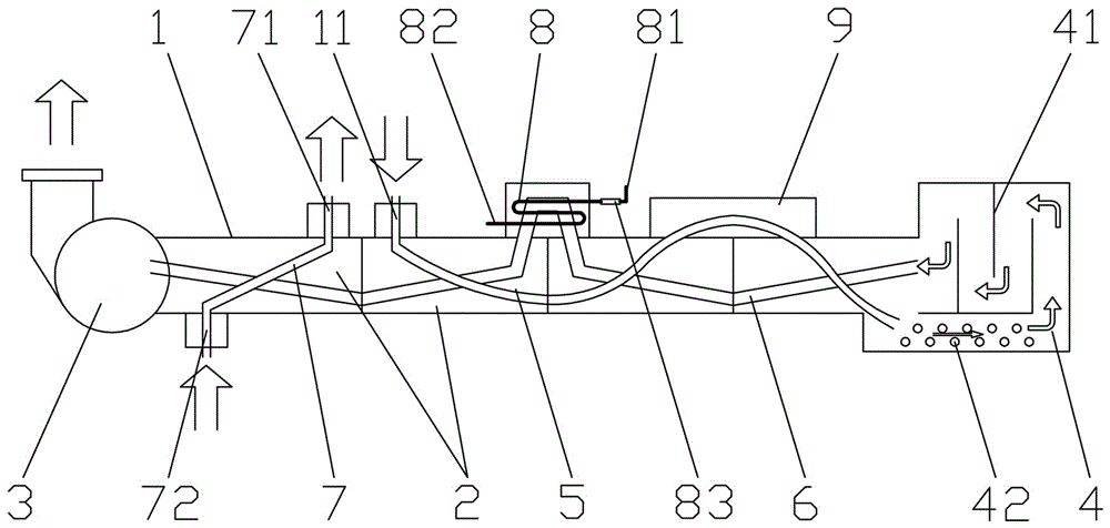
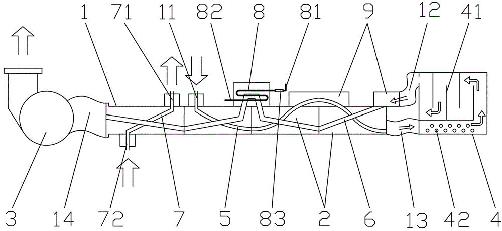
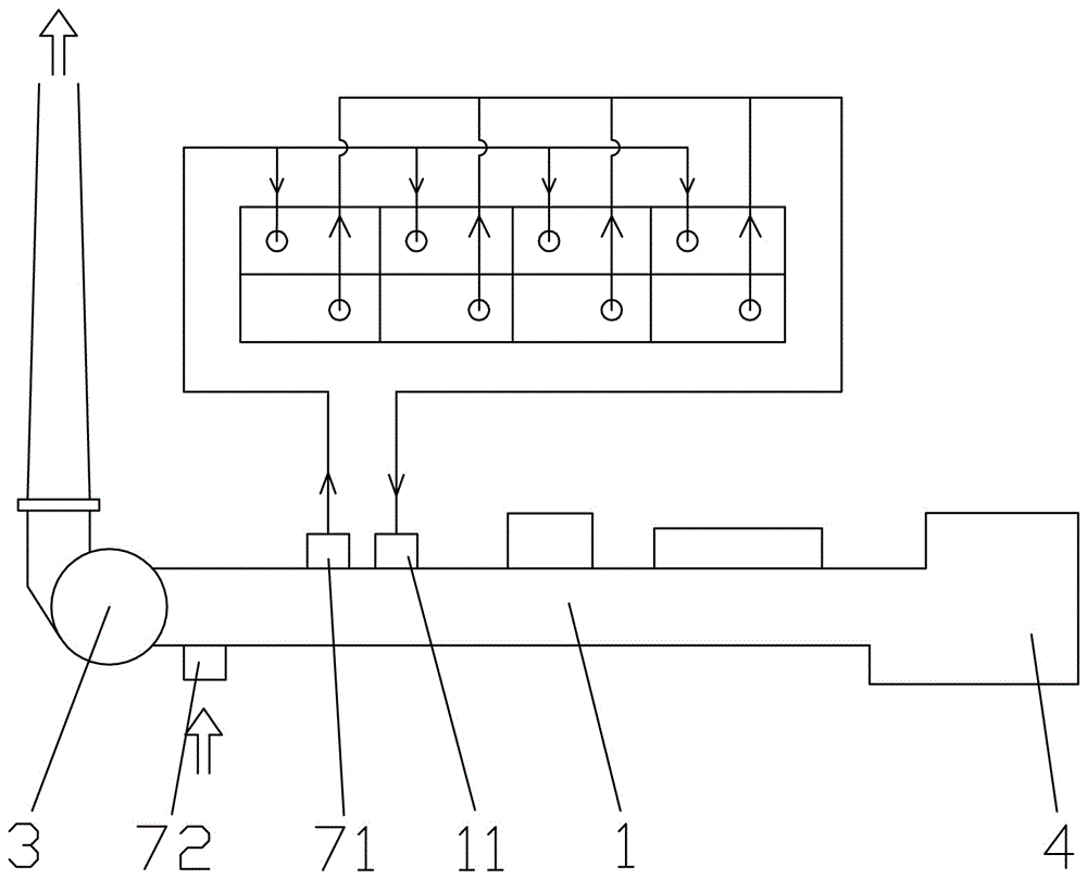
[0021] In order to make the purpose, technical solution and advantages of the present application clearer, the present invention will be further described in detail below in conjunction with the accompanying drawings and embodiments. In the ensuing description some specific details are referred to for a thorough understanding of the present invention. While the present invention may still be practiced without these specific details, the descriptions and representations herein are used by those skilled in the art to effectively convey the substance of their work to others skilled in the art. In addition, it should be noted that the terms "front side", "rear side", "left side", "right side", "upper side" and "lower side" used in the following description refer to directions in the drawings The words "inside" and "outside" respectively refer to directions toward or away from the geometric center of a specific component, and those skilled in the art who make simple and creative ad...


PUM


Abstract

The invention discloses a waste gas treatment structure applied to an incineration unit. The waste gas treatment structure comprises a heat exchange body which comprises gas-gas heat exchanger units arranged in the horizontal direction; an air exhaust fan is arranged at the left end of the heat exchange body, and a pyrolyzation chamber is arranged at the right end of the heat exchange body; and channels between adjacent gas-gas heat exchanger units of the heat exchange body are communicated and form a waste gas go passage and a gas return passage, and fresh channels are arranged in the gas-gas heat exchanger units close to the left side of the heat exchange body. As the waste gas treatment structure adopts the design that the multiple gas-gas heat exchanger units are connected in series to improve the heat exchange efficiency, the occupation space and the installation difficulty of equipment can be greatly reduced; preceding-stage high-temperature waste heat of smoke exhausted by the pyrolyzation of waste gas is used for preheating organic waste gas to be subject to pyrolyzation so that compensatory thermal energy for pyrolyzation can be saved; and later-stage high-temperature waste heat of the smoke directly generates clean and hot air which is returned to and used by a drying system of the equipment.

Description

technical field [0001] The invention relates to the technical field of organic waste gas incineration, in particular to a waste gas treatment structure applied to an incineration device. Background technique [0002] The flexible packaging and coating industry generally uses gravure printing machines and coating machines. The above equipment will emit a large amount of organic waste gas during the process of drying ink, glue and coating, causing serious pollution to the atmosphere. At present, some enterprises use regenerative incinerator (RTO) to carry out pyrolysis and oxidation treatment of organic waste gas. Since the RTO equipment needs to include two large storage tanks for storing heat storage ceramic blocks, it is huge in size, most of which exceed the height of 3 floors. Many enterprises are unable to install due to the limitation of the site, and the huge body must be installed at the user's site because it cannot be transported as a whole, which makes the installa...

Claims


Application Information

Patent Timeline
Patent Type & Authority Applications(China)
IPC IPC(8): F23J15/00F23J15/06F23J15/08F26B21/00
CPCF23J15/006F23J15/06F23J15/08F26B21/00Y02E20/30
Inventor 林建东傅红武
Owner FOSHAN ANJIEBAO ENERGY SAVING EQUIP CO LTD
Why Eureka
Try Eureka