Heat exchangers and storage tanks with heat exchangers

A technology for heat exchangers and storage tanks, which is applied in the field of material storage equipment, can solve problems such as the difficulty of finding heater leakage locations, achieve the effects of shortening maintenance time, ensuring heat exchange effects, and improving safety performance

Active Publication Date: 2019-08-20
CHNA ENERGY INVESTMENT CORP LTD +1
View PDF6 Cites 0 Cited by
  • Summary
  • Abstract
  • Description
  • Claims
  • Application Information

AI Technical Summary

Problems solved by technology

[0006] In view of this, the object of the present invention is to propose a heat exchanger and a storage tank with the heat exchanger, which can solve the existing problems such as difficulty in finding the leakage location of the heater, and further reduce the difficulty of maintenance of the heat exchanger

Method used


Image

  • Heat exchangers and storage tanks with heat exchangers
  • Heat exchangers and storage tanks with heat exchangers

Examples


Embodiment Construction

[0034] In order to make the object, technical solution and advantages of the present invention clearer, the present invention will be described in further detail below in conjunction with specific embodiments and with reference to the accompanying drawings. Wherein the same components are denoted by the same reference numerals. It should be noted that the words "front", "rear", "left", "right", "upper" and "lower" used in the following description refer to directions in the drawings. The terms "inner" and "outer" are used to refer to directions toward or away from, respectively, the geometric center of a particular component.

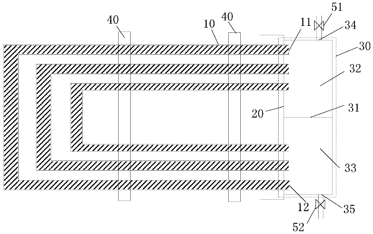
[0035] figure 1 It is a schematic diagram of a heat exchanger used in a specific embodiment of the present invention. Such as figure 1 As shown, the heat exchanger includes: heat exchange tubes 10 , tube sheets 20 and sealed chambers 30 .

[0036] The heat exchange tube 10 is used for circulation of the heat exchange medium, and the heat exchange tu...


PUM


Abstract

The invention discloses a heat exchanger and a storage groove with the heat exchanger. The heat exchanger comprises heat exchange pipes, a pipe plate and a sealing cavity. The heat exchange pipes are used for circulation of heat exchange media, and each heat exchange pipe comprises an inlet and an outlet. The heat exchange pipes are fixed to the inner side of the pipe plate. The sealing cavity is located on the outer side of the pipe plate and comprises an inlet cavity and an outlet cavity. The inlets of the heat exchange pipes stretch out of the pipe plate and communicate with the inlet cavity, and the outlets of the heat exchange pipes stretch out of the pipe plate and communicate with the outlet cavity. The inlet cavity is provided with a medium inlet, and the outlet cavity is provided with a medium outlet. According to the heat exchanger and the storage groove with the heat exchanger, the problem that the leaking position of an existing heater is difficult to find is solved, and the overhauling difficulty of the heat exchanger is further lowered.

Description

technical field [0001] The present invention relates to material storage equipment, and more particularly, to a heat exchanger and a storage tank with the heat exchanger. Background technique [0002] When producing and transporting oil, storage tanks are usually used as storage devices. Due to the high viscosity of the oil, it is easy to solidify at low temperature. A set of heating coils is installed at the bottom of the storage tank to maintain the temperature inside the storage tank. [0003] The heating coil is prone to leakage. During use, once the heating coil leaks, it is necessary to stop the operation immediately and export the oil in the storage tank. Since the heating coil is installed at the bottom of the storage tank, the storage tank needs to be thoroughly cleaned. Empty, the operator can enter the storage tank to check for leaks. Because the heating coils are mostly helical and the intervals between the coils are small, it is difficult for the operator to f...

Claims


Application Information

Patent Timeline
Patent Type & Authority Patents(China)
IPC IPC(8): F28D7/06B65D88/00
Inventor 陈秀刚于洪林李伟涛王利民
Owner CHNA ENERGY INVESTMENT CORP LTD
Why Eureka
Try Eureka