Engine cylinder internal combustion measurement system and its measurement method

A technology of engine cylinder and measurement system, which is applied in the direction of internal combustion engine test, measurement device, and measurement of rapid changes, and can solve the problems that cannot reflect the relationship between flame propagation and knocking

Inactive Publication Date: 2016-12-07
CHERY AUTOMOBILE CO LTD
View PDF7 Cites 3 Cited by
  • Summary
  • Abstract
  • Description
  • Claims
  • Application Information

AI Technical Summary

Problems solved by technology

[0002] At present, in engine test development, optical fiber means is applied to engine combustion diagnosis. Patent application number CN201510613201.3 "Measurement System and Measurement Method of Flame Propagation Velocity in Engine Cylinder" describes the detection and troubleshooting of flame propagation in cylinder by means of optical fiber; CN201

Method used


Image

  • Engine cylinder internal combustion measurement system and its measurement method
  • Engine cylinder internal combustion measurement system and its measurement method
  • Engine cylinder internal combustion measurement system and its measurement method

Examples


Embodiment Construction

[0029] The present invention will be described in detail below according to the accompanying drawings, which is a preferred embodiment among various implementations of the present invention.

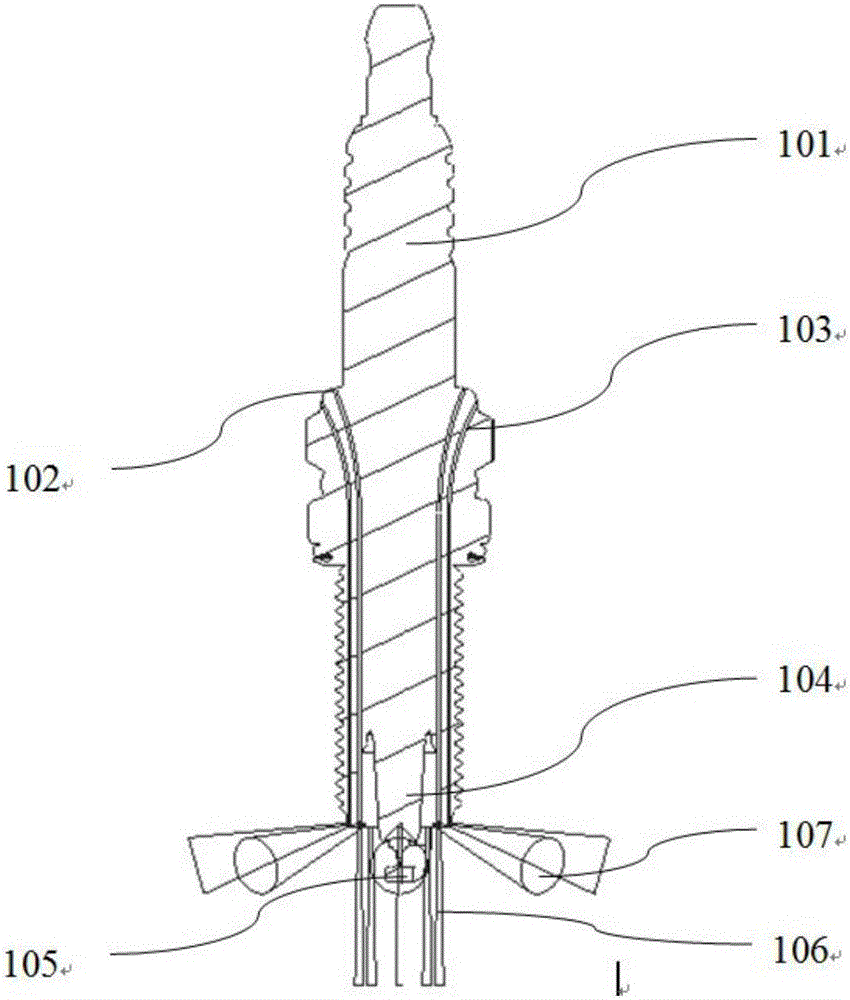
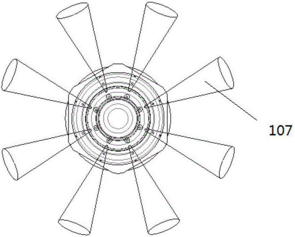
[0030] In a preferred embodiment, a measurement system and method for measuring flame propagation velocity in an engine cylinder and in-cylinder knock analysis, using the above-mentioned measurement system, includes the steps: the optical signal acquisition module collects the flame optical signal in the combustion chamber of the engine; the optical fiber The amplifier receives the optical signal transmitted by the optical signal acquisition module, amplifies the optical signal and converts the optical signal into an electrical signal; the combustion analyzer converts the signal amplified by the optical fiber amplifier into the required voltage signal according to the formula; the signal The processing module receives the voltage signal transmitted by the combustion analyzer and processes...


PUM


Abstract

The invention relates to an engine cylinder internal combustion measurement system and its measurement method. The system comprises an optical signal acquisition module, an optical fiber amplifier, a combustion analyzer and a signal processing module. The optical signal acquisition module is connected with the optical fiber amplifier through an optical fiber conduction wire and can send signals acquired by the optical signal acquisition module to the optical fiber amplifier. The optical fiber amplifier is communicatively connected to the combustion analyzer for amplifying the signals and sending the signals to the combustion analyzer. The combustion analyzer is communicatively connected to the signal processing module for transmitting signals thereto; the signal processing module is used for receiving and processing the signals. According to the invention, it is possible to directly acquire the transmission speed of flames inside the engine cylinder and the position of detonation. Based on the position of detonation and the transmission speed of the then flames, a designer can find out the explicit reasons for the detonation, such as the design for the cooling system, the air flow, and the hot spots in the combustion chamber, etc. Improvements can be made acting on these reasons to raise the phase of a set fire, increase the output performance and reduce oil consumption of the engine.

Description

technical field [0001] The invention relates to the technical field of engines, in particular to an engine cylinder combustion measurement system and a measurement method thereof. Background technique [0002] At present, in engine test development, optical fiber means is applied to engine combustion diagnosis. Patent application number CN201510613201.3 "Measurement System and Measurement Method of Flame Propagation Velocity in Engine Cylinder" describes the detection and troubleshooting of flame propagation in cylinder by means of optical fiber; CN201510021512.0 "Engine In-Cylinder Knock Position Detection System and Method" describes the use of optical fiber to detect and check the in-cylinder knock position, but the above two methods are respectively for combustion tests, due to differences in engine combustion, It does not reflect the relationship between flame propagation and detonation at the same time. Contents of the invention [0003] In view of the above technic...

Claims


Application Information

Patent Timeline
IPC IPC(8): G01L23/22G01M15/04G01P3/36
CPCG01L23/221G01M15/04G01P3/36
Inventor 琚雪明鲁新耀葛运朋牛晨晓王伟刘华龙
Owner CHERY AUTOMOBILE CO LTD
Why Eureka
Try Eureka