Urban railway transit rail to earth transition resistance testing system and method

An urban rail transit and test system technology, applied in the field of urban rail transit rail-to-ground transition resistance test system, can solve the problems of difficulty in obtaining test values, inability to meet the requirements of data simultaneity and accuracy, and difficulty in direct measurement of current.

Active Publication Date: 2016-12-07
CHINA RAILWAY FIRST SURVEY & DESIGN INST GRP
View PDF7 Cites 16 Cited by
  • Summary
  • Abstract
  • Description
  • Claims
  • Application Information

AI Technical Summary

Problems solved by technology

The site needs to provide an additional large-capacity DC power supply. The test process is complicated and requires the cooperation of multiple people to complete, which cannot meet the requirements for data simultaneity and accuracy in testing at multiple locations; the current flowing in the rail is difficult to measure directly, and it needs to be measured. The rail voltage drop of a certain length, and then divided by the rail resistance to calculate the rail current
In order to improve the measurement accuracy, the length of the rail in the pressure drop test section must be guaranteed; on the other hand, according to the evaluation requirements for stray current protection, it is generally necessary to measure the leakage resistance of the rail between two stations. It can be seen that it is difficult to obtain accurate test values ​​using this method

Method used


Image

  • Urban railway transit rail to earth transition resistance testing system and method
  • Urban railway transit rail to earth transition resistance testing system and method
  • Urban railway transit rail to earth transition resistance testing system and method

Examples


Embodiment Construction

[0074] The present invention will be described in detail below in combination with specific embodiments.

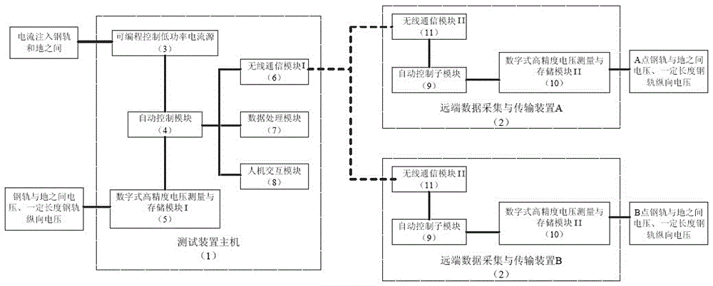
[0075] The urban rail transit rail-to-ground transition resistance testing system involved in the present invention includes a test system host 1 and a remote data acquisition and transmission device 2 that are connected to each other and perform information interaction, and complete the transmission of control commands and test data.

[0076] The test system host 1 includes a programmable control low-power current source 3, an automatic control module 4, a digital high-precision voltage measurement and storage module I5, a wireless communication module I6, a data processing module 7 and a human-computer interaction module 8; The control low-power current source 3 digital high-precision voltage measurement and storage module I5, the wireless communication module I6, the data processing module 7 and the human-computer interaction module 8 are respectively connected with the...


PUM


Abstract

The invention relates to an urban railway transit rail to earth transition resistance testing system and method. A conventional urban railway transit rail to earth transition resistance testing system cannot meet requirement of on-site tests for low power and high precision. The urban railway transit rail to earth transition resistance testing system comprises a testing system host machine and a far end data collection and transmission device that are connected with each other for information interaction; the testing system host machine comprises a programmable control low power current source, an automatic control module, a digital type high precision voltage measurement and storage module I, a wireless communication module I, a data processing module and a man-machine interaction module; the far end data collection and transmission device comprises a device automatic control submodule, a digital high precision voltage measurement and storage module II and a wireless communication module II. The portable programmable low power current source is adopted in the urban railway transit rail to earth transition resistance testing system, testing operation can be performed conveniently, data of a plurality of testing points is synchronously transmitted and processed, rail to earth transition resistance is calculated via a compensation algorithm, and urban railway transit rail to earth transition resistance can be measured in a high precision manner.

Description

technical field [0001] The invention belongs to the technical field of railway electrics, and in particular relates to an urban rail transit rail-to-ground transition resistance testing system and a method thereof. Background technique [0002] The traction power supply system of my country's urban rail transit adopts DC power supply. The electric locomotive takes current from the traction substation through the catenary. Dissipate current. Stray current will seriously corrode buried metal pipelines, steel structure and tunnel-related facilities and buildings, and long-term corrosion will seriously endanger the safety of subway operation. Article 4.2.1 of CJJ49-92 "Technical Regulations for the Protection of Stray Current Corrosion in Subway" stipulates that the transition resistance value between the subway running rail and the main structure of the tunnel (or the earth) used as backflow (measured in sections according to the block interval) And converted to the resistance...

Claims


Application Information

Patent Timeline
Patent Type & Authority Applications(China)
IPC IPC(8): G01R27/14G01R27/18
CPCG01R27/14G01R27/18
Inventor 黄文勋丁大鹏郭强林志海陶临生蒋功连曲尚开杲秀芳肖梓林黄晓静
Owner CHINA RAILWAY FIRST SURVEY & DESIGN INST GRP
Why Eureka
Try Eureka