Wide angle lens
A wide-angle lens, lens technology, applied in optical components, instruments, optics, etc., can solve problems such as residual resolution, drop, and inability to stabilize lens bonding
- Summary
- Abstract
- Description
- Claims
- Application Information
AI Technical Summary
Problems solved by technology
Method used
Image

Examples
Embodiment approach 1
[0052]Fig. 1 (a), Fig. 1 (b), Fig. 1 (c) are explanatory diagrams of a wide-angle lens related to Embodiment 1 of the present invention, Fig. 1 (a) is an explanatory diagram showing a lens structure, Fig. 1 (b ) is an explanatory diagram showing physical properties of each surface, etc., and FIG. 1( c ) is an explanatory diagram showing aspheric coefficients. 2( a ), FIG. 2( b ), and FIG. 2( c ) are explanatory diagrams showing aberrations of the wide-angle lens according to Embodiment 1 of the present invention, and FIG. 2( a ) is an explanatory diagram of lateral chromatic aberration. , FIG. 2(b) is an explanatory diagram of field curvature aberration, and FIG. 2(c) is an explanatory diagram of distortion aberration. 3(a), FIG. 3(b), FIG. 3(c), FIG. 3(d), and FIG. 3(e) are explanatory diagrams showing lateral aberration of the wide-angle lens according to Embodiment 1 of the present invention, Figure 3(a) shows the lateral aberration in the tangential direction (Y direction...
Embodiment approach 2
[0092]4( a ), FIG. 4( b ), and FIG. 4( c ) are explanatory diagrams of the wide-angle lens according to Embodiment 2 of the present invention. 4( a ) is an explanatory diagram showing a lens structure, FIG. 4( b ) is an explanatory diagram showing physical properties of each surface, etc., and FIG. 4( c ) is an explanatory diagram showing aspheric coefficients. 5( a ), FIG. 5( b ), and FIG. 5( c ) are explanatory diagrams showing aberrations of the wide-angle lens according to Embodiment 2 of the present invention, and FIG. 5( a ) is an explanatory diagram of lateral chromatic aberration. , FIG. 5(b) is an explanatory diagram of field curvature aberration, and FIG. 5(c) is an explanatory diagram of distortion aberration. 6(a), FIG. 6(b), FIG. 6(c), FIG. 6(d), and FIG. 6(e) are explanatory diagrams showing lateral aberration of the wide-angle lens according to Embodiment 2 of the present invention, Figure 6(a) shows the lateral aberration in the tangential direction (Y directi...
Embodiment approach 3
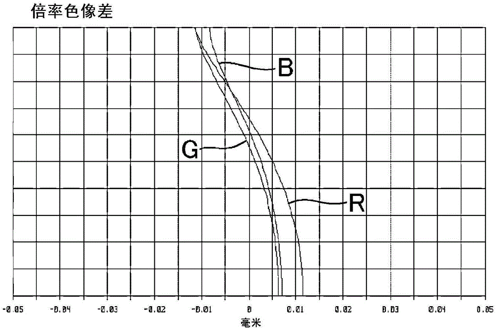
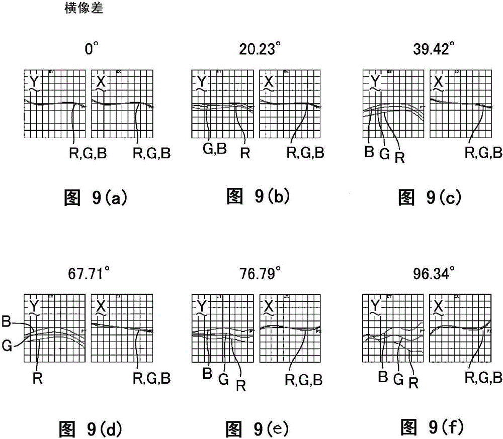
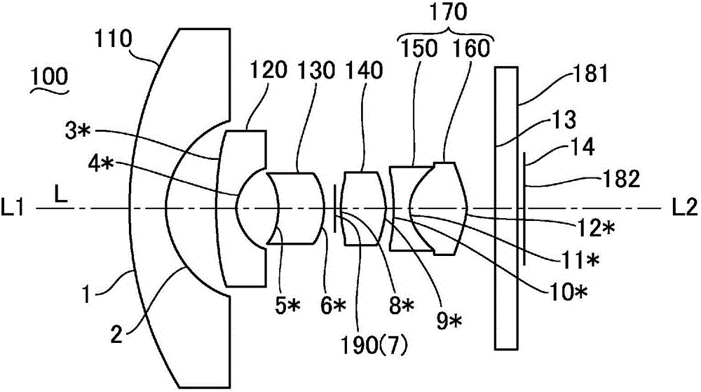
[0120] Fig. 7 (a), Fig. 7 (b), Fig. 7 (c) are explanatory diagrams of the wide-angle lens related to Embodiment 3 of the present invention, Fig. 7 (a) is the explanatory diagram showing lens structure, Fig. 7 (b ) is an explanatory diagram showing physical properties of each surface, etc., and FIG. 7( c ) is an explanatory diagram showing aspheric coefficients. 8( a ), FIG. 8( b ), and FIG. 8( c ) are explanatory diagrams showing aberrations of the wide-angle lens according to Embodiment 3 of the present invention, and FIG. 8( a ) is an explanatory diagram of lateral chromatic aberration. , FIG. 8(b) is an explanatory diagram of field curvature aberration, and FIG. 8(c) is an explanatory diagram of distortion aberration. 9( a ), FIG. 9( b ), FIG. 9( c ), FIG. 9( d ), FIG. 9( e ), and FIG. 9( f ) are horizontal images showing the wide-angle lens according to Embodiment 3 of the present invention. As an explanatory diagram of the difference, Fig. 9(a) shows the lateral aberrati...
PUM
 Abstract
Description
Claims
Application Information
 - R&D
- Intellectual Property
- Life Sciences
- Materials
- Tech Scout
- Unparalleled Data Quality
- Higher Quality Content
- 60% Fewer Hallucinations
Browse by: Latest US Patents, China's latest patents, Technical Efficacy Thesaurus, Application Domain, Technology Topic, Popular Technical Reports.
© 2025 PatSnap. All rights reserved.Legal|Privacy policy|Modern Slavery Act Transparency Statement|Sitemap|About US| Contact US: help@patsnap.com