
Control method and device of infrared humidifying device in water tank

A humidification device and control method technology, applied in heating mode, program control, computer control and other directions, can solve the problem of uneven local heating, and achieve the effect of reducing maintenance downtime and humidification failure rate

Active Publication Date: 2016-12-07
GREE ELECTRIC APPLIANCES INC
View PDF6 Cites 16 Cited by
  • Summary
  • Abstract
  • Description
  • Claims
  • Application Information

AI Technical Summary

Problems solved by technology

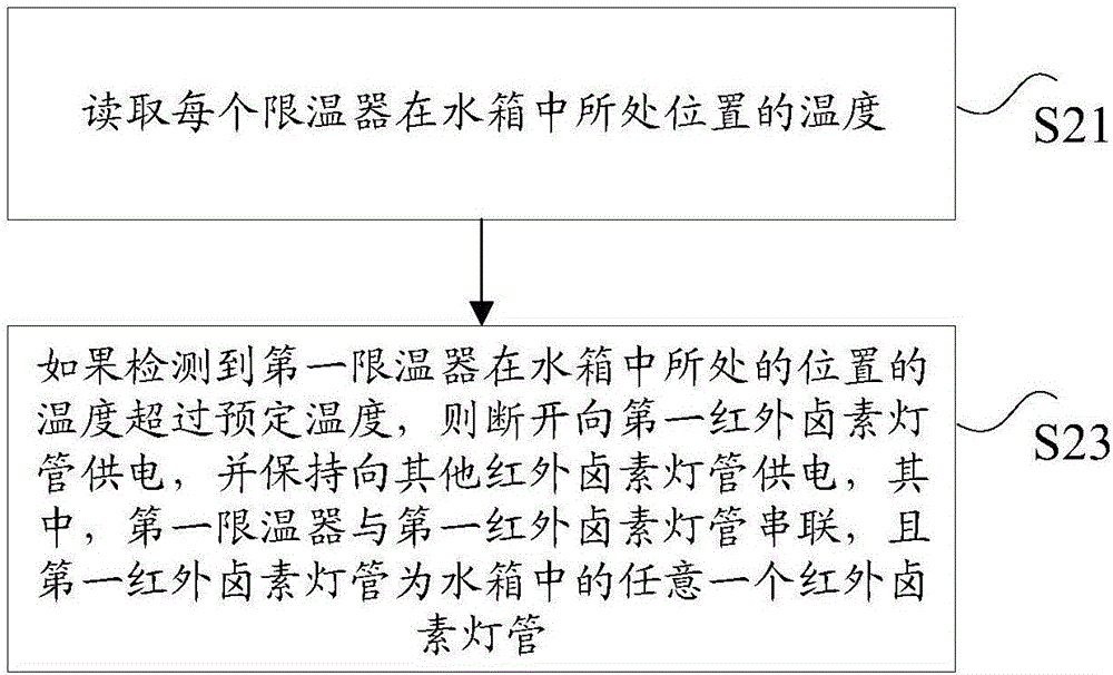
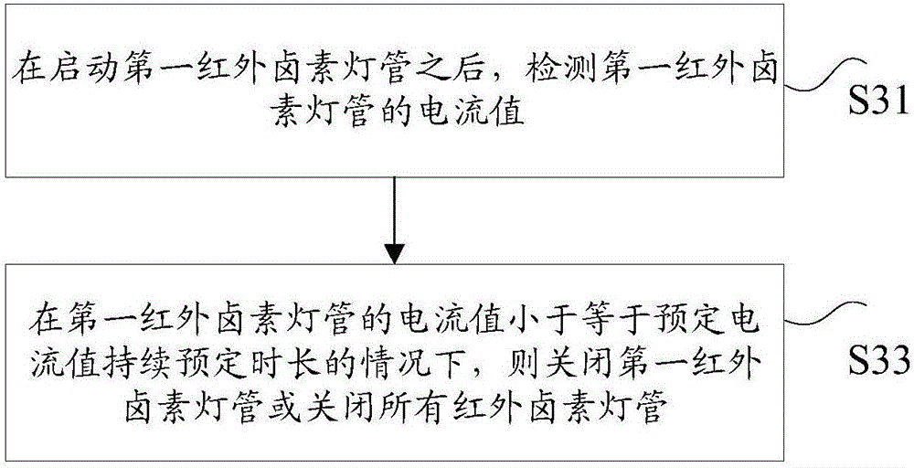
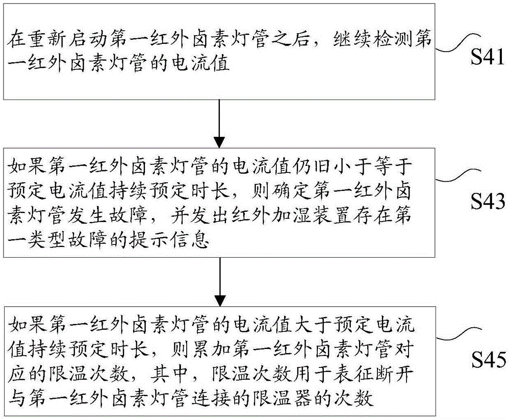
[0006] The embodiment of the present invention provides a control method and device for an infrared humidifying device in a water tank, so as to at least solve the problem that the existing infrared humidifying device stops humidifying due to the malfunction of the anti-dry heating temperature protection switch due to local uneven heating technical issues

Method used


Image

  • Control method and device of infrared humidifying device in water tank
  • Control method and device of infrared humidifying device in water tank
  • Control method and device of infrared humidifying device in water tank

Examples


Embodiment 2

[0086] According to an embodiment of the present invention, an embodiment of a control device for an infrared humidifying device in a water tank is also provided. The method for controlling the infrared humidifying device in the water tank in Embodiment 1 of the present invention can be implemented in the device in Embodiment 2 of the present invention.

[0087] Figure 8 It is a schematic diagram of a control device of an infrared humidifying device in a water tank according to an embodiment of the present invention. The infrared humidifying device includes at least two infrared halogen lamp tubes connected in parallel, and each infrared halogen lamp tube is connected to at least one temperature limiter. Each temperature limiter is located at a different location within the tank, such as Figure 8 As shown, the device includes: a temperature limiter 402 and a processor 404 .

[0088] Wherein, the temperature limiter 402 is connected with each infrared halogen tube, and is u...

Embodiment 3

[0097] According to an embodiment of the present invention, an embodiment of a control device for an infrared humidifying device in a water tank is also provided. The method for controlling the infrared humidifying device in the water tank in Embodiment 1 of the present invention can be implemented in the device in Embodiment 3 of the present invention.

[0098] Figure 9 It is a schematic diagram of a control device of an infrared humidifying device in a water tank according to an embodiment of the present invention. The infrared humidifying device includes at least two infrared halogen lamp tubes connected in parallel, and each infrared halogen lamp tube is located at a different position in the water tank, such as Figure 9 As shown, the device includes: a first detection module 902 and a processing module 904 .

[0099] Wherein, the first detection module 902 is used to read the temperature at the position of each temperature limiter in the water tank;

[0100] The proce...


PUM


Abstract

The invention discloses a control method and device of an infrared humidifying device in a water tank. The method comprises the steps that the temperature of the position where each temperature limiter is located in the water tank is read; if it is detected that the temperature of the position where the first temperature limiter is located exceeds a preset temperature, electricity supplied to a first infrared halogen lamp is cut off, and electricity is kept to be supplied to other infrared halogen lamps, and the first temperature limiter is in series connection with the first infrared halogen lamp which is any infrared halogen lamp in the water tank. According to the control method and device of the infrared humidifying device in the water tank, the technical problem that for an existing infrared halogen lamp, due to the fact that local heating is nonuniform, and a dry burning-resistant temperature protection switch acts by mistake, the infrared humidifying device is made to stop humidifying is solved.

Description

technical field [0001] The invention relates to the field of electrical automation control, in particular to a control method and device for an infrared humidifying device in a water tank. Background technique [0002] In this field, infrared humidification uses infrared radiation energy to heat the water in the water storage tank, so that the water evaporates quickly without boiling, and produces clean steam for humidification. It does not require high water quality, so it has become the latest industrial humidification equipment. . The principle of infrared humidification is mainly to use infrared thermal radiation to make the water surface generate heat under the action of infrared rays and then evaporate, and then transport the steam to the space through the air supply system, so as to achieve the purpose of humidification. [0003] However, due to the high temperature of the infrared halogen lamp tube when it works, when the liquid level of the water in the water stora...

Claims


Application Information

Patent Timeline
Patent Type & Authority Applications(China)
IPC IPC(8): G05B19/048F24F11/00F24F11/02
CPCG05B19/048
Inventor 缪玉珍陈晓江
Owner GREE ELECTRIC APPLIANCES INC
Learn More