A micro-motion stage used in a photolithography motion stage system and its control method

A technology of moving stage and micro-moving stage, which is applied in the field of semiconductors, can solve the problems of insufficient torsional travel, inapplicability, and difficult control, etc., and achieve the effect of reducing requirements, reducing output, and reducing demand

Active Publication Date: 2019-12-20
SHANGHAI MICRO ELECTRONICS EQUIP (GRP) CO LTD
View PDF4 Cites 0 Cited by
  • Summary
  • Abstract
  • Description
  • Claims
  • Application Information

AI Technical Summary

Problems solved by technology

Due to the larger size of the 6G workpiece table, the requirements for the micro-motion table are also higher, so the original design for 4.5G is no longer suitable for 6G
[0004] like figure 1 As shown, the existing micro-motion table structure proposed for 4.5G includes a micro-motion plate 1, three vertical motors 2 and three gravity compensators 3 are respectively arranged under the micro-motion plate 1, and two oppositely arranged The Rz motor 4 is used to drive the movement of the micro-motion plate 1 in the Z direction and the Rz direction. This structure restricts the control bandwidth of the Z direction due to the first-order structural modal frequency of the micro-motion plate 1. For example, to achieve a control bandwidth of 50 Hz, the micro The frequency of the moving plate 1 must reach 150 Hz, and it is inevitable to use materials such as ceramics to achieve greater rigidity in the design of parts, which is not economical; in the prior art, ring air bearings 5 ​​and hinged air bearings 6 are used to decouple Rx and Ry Directional torque, such as figure 2 As shown, when the hinged air bearing 6 generates torque in the Rx and Ry directions, the air film thickness L will change. If the torque is too large, the air film thickness L will be too small, which will affect the air bearing function and the torsional stroke will be insufficient. ; Additionally, if image 3 As shown, the center of the existing ring air bearing 5 coincides with the centroid of the micro-movement plate 1, the eccentric moment is relatively large, it is difficult to control, and two Rz motors 4 are required to generate a large thrust (respectively F Rz1 and F Rz2 ), used to balance the inertial force generated by the horizontal acceleration

Method used


Image

  • A micro-motion stage used in a photolithography motion stage system and its control method
  • A micro-motion stage used in a photolithography motion stage system and its control method
  • A micro-motion stage used in a photolithography motion stage system and its control method

Examples


Embodiment Construction

[0028] In order to make the above objects, features and advantages of the present invention more clearly understood, the specific embodiments of the present invention will be described in detail below with reference to the accompanying drawings. It should be noted that the accompanying drawings of the present invention are all in a simplified form and use inaccurate scales, and are only used to facilitate and clearly assist the purpose of explaining the embodiments of the present invention.

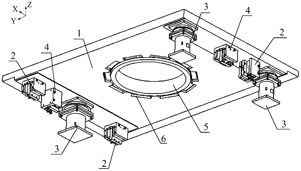
[0029] The micro-movement table for the lithography motion table system provided by the present invention is installed on the moving part 20 of the workpiece table. Specifically, the motion table includes a hanging frame at the bottom, and two parallel Y The guide rails are Y-direction sliders that are respectively fixed on the Y-direction guide rails and can slide along the Y-direction guide rails. An X-direction guide rail is erected between the two Y-direction sliders, and the moving pa...


PUM


Abstract

The invention relates to a micro-motion platform for a photo-etching motion platform system and a control method thereof. The micro-motion platform is mounted on a motion part of a workpiece platformand comprises a micro-motion plate and four vertical motors arranged at the bottom of the micro-motion plate; the four vertical motors are arranged at two sides of the micro-motion plate; each vertical motor is correspondingly provided with a sensor; an Rz motor is arranged between the two vertical motors at the same side; an air-floating decoupling device is arranged at a part which is no more than 30mm far away from the mass center of the micro-motion plate. According to the micro-motion platform provided by the invention, the four vertical motors and the four sensors are adopted to realizeredundancy control according to a redundancy driving principle and a redundancy measurement principle and the requirements on the frequency of the micro-motion plate are reduced; only if the frequencyof the micro-motion plate reaches about 120Hz, the bandwidth of 50Hz can be obtained; the requirements on valuable materials are reduced and the cost is reduced; the air-floating decoupling device isclose to the mass center of the micro-motion plate, but not the form center of the micro-motion plate, so that the output power of the Rz motor is extremely reduced.

Description

technical field [0001] The invention relates to the field of semiconductors, in particular to a micro-moving stage used in a lithography moving stage system and a control method thereof. Background technique [0002] The sixth-generation step-scan projection lithography machine (hereinafter referred to as 6G) is a special equipment for making TFT (Thin Film Transistor, English full name: Thin Film Transistor) circuits for flat panel display devices. It is compatible with the 5.5th generation step-scan projection lithography machine (1500×1300mm) size substrate. The imaging resolution of the step-scan projection lithography machine is 1.7um (based on GHI Line) / 1.5um (based on I Line, optional), the overlay accuracy is 0.5um, and the CDU index is 7%@BF, BE, 10%@ TF, BE, focal depth 8um (based on GHI Line) / 6um (based on I Line, optional), scanning speed 0.8m / s, compared with the 4.5th generation step-scan projection lithography machine (hereinafter referred to as 4.5G), The 6...

Claims


Application Information

Patent Timeline
Patent Type & Authority Patents(China)
IPC IPC(8): G03F7/20
CPCG03F7/70716G03F7/70725
Inventor 王理华廖飞红朱岳彬葛黎黎张魁斌
Owner SHANGHAI MICRO ELECTRONICS EQUIP (GRP) CO LTD
Why Eureka
Try Eureka