Eureka AIR delivers breakthrough ideas for toughest innovation challenges, trusted by R&D personnel around the world.

Control method and circuit of photoelectric induction knob

A technology of photoelectric induction and control method, which is applied in the direction of electrical program control, sequence/logic controller program control, etc., can solve the problems of restricting the design of the overall structure device, affecting the overall performance of the adjustment knob, and being difficult to meet the increasing needs, etc., to achieve Low manufacturing cost, meet PCB miniaturization design requirements, and avoid the effect of being easily affected by the environment

Active Publication Date: 2016-12-07
FORYOU GENERAL ELECTRONICS
View PDF9 Cites 7 Cited by
  • Summary
  • Abstract
  • Description
  • Claims
  • Application Information

AI Technical Summary

Problems solved by technology

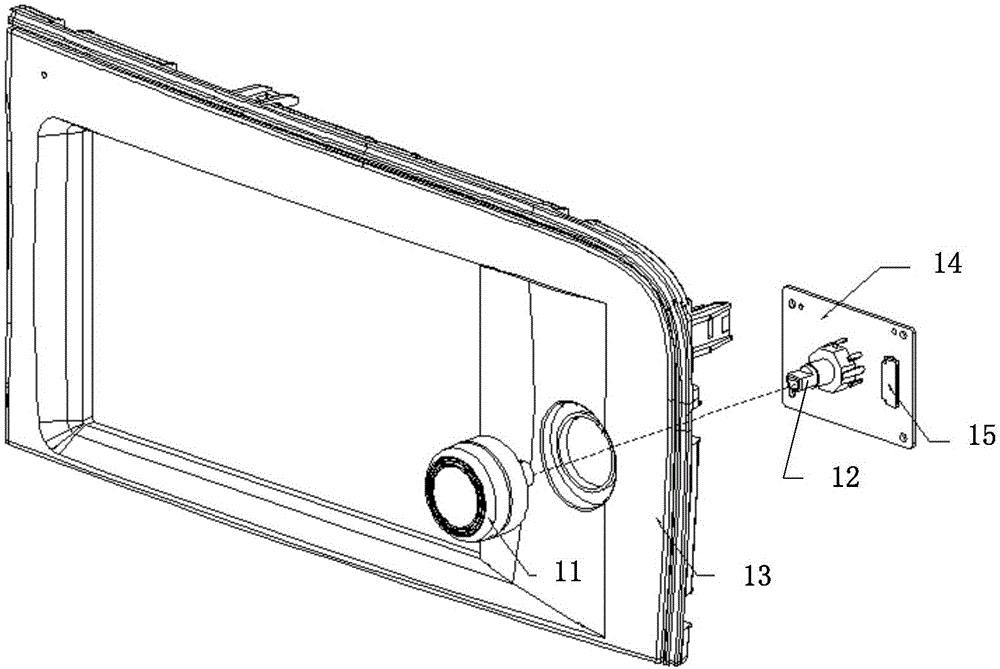
It can be seen that the traditional variable potentiometer (or encoder) 12 has limited the design of its overall structural device due to its large device footprint and is difficult to meet the increasing PCB miniaturization requirements.
[0005] In addition, since the variable potentiometer (or encoder) 12 needs to be installed on the PCB 14 for fixing and connecting to the electronic circuit, and then the knob 11 is installed for supporting use, such a fixed wired connection is easily affected by external forces and the connection is interrupted. And other problems will inevitably affect the overall performance of the adjustment knob

Method used

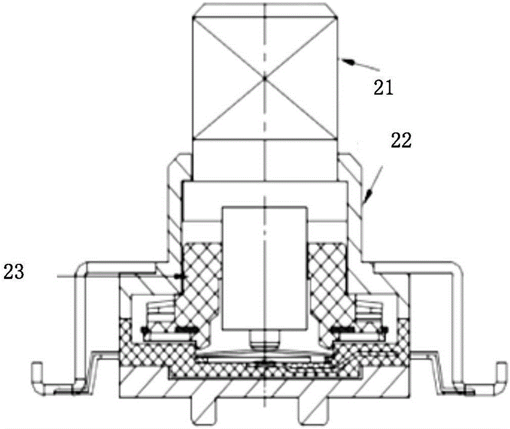

Image

  • Control method and circuit of photoelectric induction knob
  • Control method and circuit of photoelectric induction knob
  • Control method and circuit of photoelectric induction knob

Examples


Embodiment Construction

[0043] The following will clearly and completely describe the technical solutions in the embodiments of the present invention with reference to the drawings in the embodiments of the present invention. It should be noted that in this article, relational terms such as first and second are only used to distinguish one entity or operation from another entity or operation, and do not necessarily require or imply that there is a relationship between these entities or operations. There is no such actual relationship or sequence.

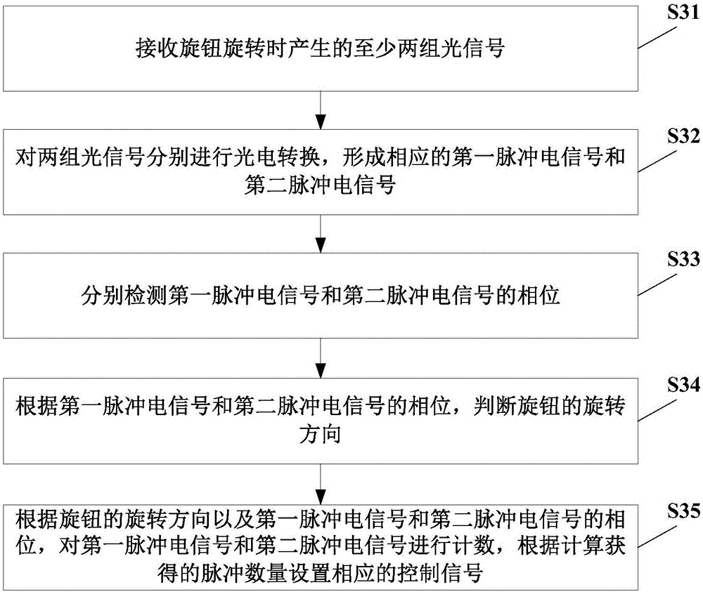
[0044] see image 3 , is a flow chart of the steps of an embodiment of the method for controlling the photoelectric sensor knob provided by the present invention.

[0045] In this embodiment, the control method of the photoelectric sensor knob mainly includes the following steps S31-S35:

[0046] Step S31: receiving at least two sets of optical signals generated when the knob is rotated;

[0047] During specific implementation, the two groups of optical s...


PUM


Abstract

The invention discloses a control method of a photoelectric induction knob. The control method comprises the steps that two or more groups of optical signals generated during rotation of the knob are received, the two groups of optical signals are subjected to photoelectric conversion, and first pulse electric signals and second pulse electric signals corresponding to the two groups of optical signals respectively are formed; the phase of the first pulse electric signals and the phase of the second pulse electric signals are detected respectively; the rotating direction of the knob is judged according to the phase of the first pulse electric signals and the phase of the second pulse electric signals; the first pulse electric signals and the second pulse electric signals are counted according to the rotating direction of the knob, the phase of the first pulse electric signals and the phase of the second pulse electric signals, and corresponding control signals are set according to the calculated number of pulses. The invention further provides a control circuit of the photoelectric induction knob. By means of the technical scheme, the service life of the knob can be prolonged, occupied space can be reduced, the wireless connection functional control is achieved, the requirement for PCB miniaturization is met, the structure is simple and effective, practicability is high, and cost is low.

Description

technical field [0001] The invention relates to the technical field of electronic devices, in particular to a control method and circuit of a photoelectric induction knob. Background technique [0002] Adjusting knobs are widely used in various electronic products, such as volume knobs for car audio, radio station selection knobs, air volume / temperature adjustment knobs for air conditioners, etc. [0003] The traditional adjusting knob device usually adopts a structure similar to a variable potentiometer or an encoder to realize its function. see figure 1 , is a schematic diagram of an installation structure of an existing rotary adjustment device. Specifically, the knob 11 and the variable potentiometer (or encoder) 12 are combined and fixed on the panel 13, and the variable potentiometer (or encoder) 12 is realized by being installed on the PCB (printed circuit board) 14. The control function obtains signals such as power supply through the connector 15 on the PCB14. i...

Claims


Application Information

Patent Timeline
Patent Type & Authority Applications(China)
IPC IPC(8): G05B19/06
CPCG05B19/06
Inventor 李远辉刘金权
Owner FORYOU GENERAL ELECTRONICS
Why Eureka
Eureka Blog
Learn More