[0059] In order to make the objectives, technical solutions, and advantages of the present invention clearer, the following further describes the present invention in detail with reference to specific embodiments and drawings.
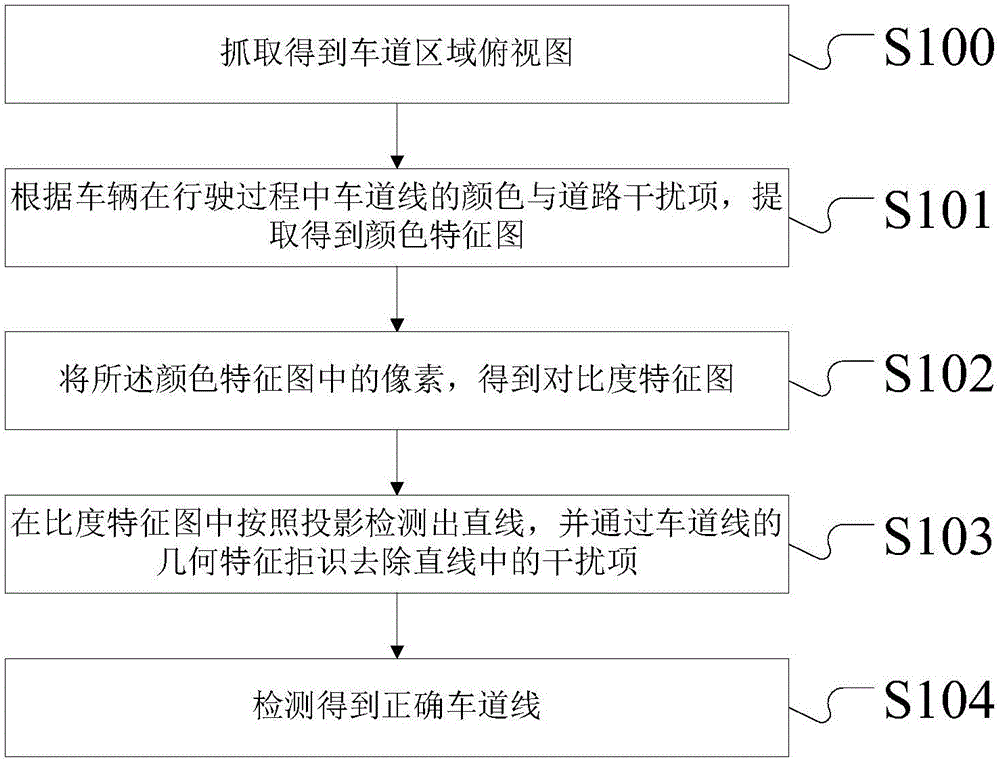
[0060] Please refer to figure 1 It is a schematic flow diagram of a lane line detection method based on multi-feature fusion in an embodiment of the present invention.
[0061] In this embodiment, the multi-feature fusion lane line detection method includes the following steps:
[0062] In step S100, a top view of the lane area is captured; in the step S100, after the vehicle enters the lane, the image can be collected by the advanced driving assistance system in the vehicle. The advanced driving assistance system is referred to as ADAS. It uses a variety of sensors installed on the car to collect environmental data inside and outside the car at the first time, and perform technical processing such as identification, detection and tracking of static and dynamic objects, so that the driver can be Active safety technology that detects possible dangers in a short time to attract attention and improve safety. Generally speaking, the sensors used by ADAS mainly include cameras, radars, lasers and ultrasonics, etc., which can detect light, heat, pressure or other variables used to monitor the state of the car. They are usually located on the front and rear bumpers, side mirrors, and steering rods of the vehicle. Inside or on the windshield. ADAS's reminder functions to the driver include anti-front vehicle collision warning, lane departure warning, and pedestrian collision warning.
[0063] In some embodiments, the top view refers to an image that simulates a top view perspective. In the top view perspective, lane lines are parallel, which is easier to detect. The usual way to obtain the top view is to select the lane area in the original image, and then obtain the inverse perspective transformation.
[0064] In some embodiments, the inverse perspective transformation uses the function of solving the transformation formula in OPENCV, and inputs the corresponding 4 points of the original image and the transformed image to obtain the transformation matrix. Then input perspective Transform with the obtained matrix to transform a set of points:
[0065] In some embodiments, the reverse perspective is to project the acquired lane image onto a new viewing plane to obtain a top view.
[0066] In some embodiments, the top view refers to an image that simulates a top view perspective. In the top view perspective, lane lines are parallel and easy to detect.
[0067] In some embodiments, when selecting a lane area in the original image, a white or yellow lane line is selected.
[0068] The functions and beneficial effects of the above step S100 include at least: the top view refers to an image that simulates the top view perspective, and the lane lines are parallel in the top view perspective, which is easier to detect.
[0069] Step S101 extracts and obtains a color feature map according to the color of the lane line and road interference items during the driving of the vehicle; the step also includes a process of obtaining prior information in advance.
[0070] In some embodiments, the prior information includes, but is not limited to, for Chinese road conditions, the colors of lane lines are mainly divided into white and yellow.
[0071] In some embodiments, the a priori information includes, but is not limited to, the interference of lights of various colors after the vehicle enters the highway.
[0072] In some embodiments, the color light interference includes, but is not limited to, the red glare of brake lights, the reflection of red and green lights of traffic lights on the road surface, etc. The main color components are red and green.
[0073] As a preference in this embodiment, the a priori information includes the lane line color and the color of the road interference item. The lane line color is composed of white and yellow; the color of the road interference item includes red and green.
[0074] As a preference in this embodiment, the road disturbance items include the red glare of brake lights, the reflection of red and/or green lights of traffic lights on the road surface, and the white color caused by high beams of vehicles on the opposite side at night. One or more of glare, glare caused by backlighting, and white railings on the roadside.
[0075] The functions and beneficial effects of the above step S101 include at least: using color information to enhance lane lines and suppress interference items.
[0076] Based on the above prior information, the extracted color feature map can be summarized as enhancing white and yellow, and suppressing red and green. In this embodiment, after a lot of experiments, a very simple and effective color filter operator is designed, which will not consume more computing resources due to processing RGB images.
[0077] As a preference in this embodiment, according to the prior information, the pixels in the RGB image of the top view of the lane area are calculated according to the following color filter operator to obtain the color feature map
[0078] C i , j = 2 × R i , j × G i , j R i , j + G i , j - | R i , j - G i , j |
[0079] Among them, R represents the red channel, G represents the green channel, and i and j represent the abscissa and ordinate of the pixel.
[0080] Step S102 obtains a contrast feature map from the pixels in the color feature map; because in the color feature map, the feature value corresponding to the lane line is larger than the feature value of the road surface, and the width of the lane line is fixed. However, the pixel points of the lane line are all lane lines within a certain range up and down, and the lane lines outside a certain width on the left and right are no longer lane lines. In addition, the color feature values of the road surface are similar, and there will be no large fluctuations.
[0081] In some embodiments, the pixels in the color feature map are passed through the following formula through the contrast operator to obtain the contrast feature map
[0082] D i , j = C i , j + C i , j + ϵ + C i , j - ϵ 2 - C i - ϵ , j - C i + ϵ , j - | C i - ϵ , j - C i + ϵ , j |
[0083] Among them, ε is the pixel width of the preset lane line in the color feature map.
[0084] Preferably, the ε value is 5.
[0085] The function and beneficial effects of the above step S102 include at least: a. The characteristic value corresponding to the lane line is larger than the characteristic value of the road surface, and the width of the lane line is fixed. b. For the pixel points of the lane line, within a certain range up and down, they are all lane lines, and outside a certain width on the left and right are no longer lane lines. c. The color characteristic values of the road surface are similar, and there will be no big fluctuations. Thus, an accurate contrast characteristic map can be obtained.
[0086] In step S103, a straight line is detected in the ratio feature map according to the projection, and the interference item in the straight line is removed through the geometric feature rejection of the lane line;
[0087] In some embodiments, the method of detecting a straight line according to projection in the ratio feature map is specifically:
[0088] Set the vertical direction to 0 degrees, take the projection angle β from -15 degrees to 15 degrees, calculate the cumulative value of the contrast feature map in the y-axis direction at different angles, and obtain a one-dimensional array on the x-axis;
[0089] If there is a local peak point, select the x coordinate of the local peak point of the array and the corresponding projection angle β to calibrate the straight line L i.
[0090] In some embodiments, the method of removing interference items in the straight line through the geometric feature rejection of the lane line is specifically as follows:
[0091] According to the relative fixed position of the lane line on the road surface, if the detected straight line is an interference item, when changing lanes or turning, the x-coordinate and projection angle β in the lane line change greatly, and the interference item is removed.
[0092] The function and beneficial effects of the above step 103 include at least: Since the lane line is already very prominent on the contrast feature map, a simple and efficient projection method can be selected by using straight line detection.
[0093] In some embodiments, the geometric features of the lane line are rejected. Since the position of the lane line on the road surface is relatively fixed, the x-coordinate and the angle β of the lane line change steadily even when cutting or turning.
[0094] In some embodiments, if the light emitted by the high beam of an oncoming car, during the relative movement, the angle β in the image will change dramatically in a short time, then the interference line can be found
[0095] Step S104 detects the correct lane line.
[0096] Please refer to figure 2 It is a schematic structural diagram of a multi-feature fusion lane line detection system in an embodiment of the present invention.
[0097] The multi-feature fusion lane line detection system in this embodiment includes:
[0098] First, image information is collected. The image can be sensed by a sensor installed outside the vehicle, and the obtained target image is input into the lane area top view detection unit 1 to capture the lane area top view when the vehicle enters the lane;
[0099] The color feature map extraction unit 2 is used for extracting and obtaining a color feature map according to the color of the lane line and road interference items during the driving of the vehicle;
[0100] The contrast feature map extraction unit 3 is used to obtain a contrast feature map from the pixels in the color feature map;
[0101] The straight line detection unit 4 is used to detect straight lines in the ratio characteristic map according to projection;
[0102] The geometric change feature rejection unit 5 is used to remove the interference items in the straight line through the geometric feature rejection of the lane line, detect the correct lane line, and then output the detection result of the lane line.
[0103] In some embodiments, video data is collected by a visual sensor (camera) installed in front of the vehicle, and then the position of the lane line is detected, and the corresponding warning strategy is made. Finally, the driver is prompted by voice whether the vehicle has deviated from the lane. Early warning strategies can be lane departure warning, lane exceeding warning, and lane pressure warning.
[0104] In some embodiments, in the lane area top view detection unit 1,
[0105] In some embodiments, the color feature map extraction unit 2 calculates the pixels in the RGB image of the top view of the lane area according to the following color filter operator to obtain the color feature map according to the prior information
[0106] C i , j = 2 × R i , j × G i , j R i , j + G i , j - | R i , j - G i , j |
[0107] Among them, R represents the red channel, G represents the green channel, and i and j represent the abscissa and ordinate of the pixel.
[0108] Wherein, the prior information includes the lane line color and the color of a road interference item, the lane line color is composed of white and yellow; the color of the road interference item includes red and green.
[0109] Wherein, the road disturbance items include the red glare of brake lights, the reflection of red and/or green light of traffic lights on the road surface, the white glare caused by the high beams of vehicles on the opposite side at night, and the white glare caused by backlighting. One or more of the bright glare, the white railings on the roadside.
[0110] In some embodiments, the contrast feature map extraction unit 3 passes the pixels in the color feature map through the following formula through a contrast operator to obtain the contrast feature map
[0111] D i , j = C i , j + C i , j + ϵ + C i , j - ϵ 2 - C i - ϵ , j - C i + ϵ , j - | C i - ϵ , j - C i + ϵ , j |
[0112] Where ε is the pixel width of the preset lane line in the color feature map, and the ε value is 5.
[0113] In some embodiments, the method of detecting the straight line unit 4 according to projection in the ratio feature map is specifically: set the vertical direction to 0 degrees, take the projection angle β from -15 degrees to 15 degrees, and calculate separately The cumulative value of the contrast feature map in the y-axis direction at different angles is obtained, and a one-dimensional array on the x-axis is obtained; if a local peak point occurs, the x coordinate of the local peak point of the array and the corresponding projection angle β are selected to calibrate the straight line L i.
[0114] In some embodiments, the geometric change feature rejection unit 5 uses the geometric feature rejection of the lane line to remove the interference items in the straight line: according to the relative fixed position of the lane line on the road surface, if the detected straight line is interference When changing lanes or turning, the x-coordinate and projection angle β in the lane line change greatly, so the interference term is removed.
[0115] Please refer to image 3 It is a schematic structural diagram of an advanced driving assistance system in an embodiment of the present invention.
[0116] The advanced driving assistance system is characterized by comprising a multi-feature fusion lane line detection system 10, a visual sensor 11 installed on the car, and an early warning unit 12,
[0117] The visual sensor 11 is used to collect video data;
[0118] The multi-feature fusion lane line detection system 10 is used to detect the position of the lane line;
[0119] The multi-feature fusion lane line detection system includes a lane area top view detection unit, a color feature map extraction unit, a contrast feature map extraction unit, a detection line unit, and a geometric change feature rejection unit,
[0120] The lane area top view detection unit is used to capture the lane area top view when the vehicle enters the lane;
[0121] The color feature map extraction unit is used to extract the color feature map according to the color of the lane line and road interference items during the driving of the vehicle;
[0122] The contrast feature map extraction unit is used to obtain a contrast feature map from the pixels in the color feature map;
[0123] The detection straight line unit is used to detect straight lines in the ratio characteristic map according to projection;
[0124] The geometric change feature rejection unit is used to remove the interference items in the straight line through the geometric feature rejection of the lane line, and detect the correct lane line;
[0125] The warning unit 12 is used for judging whether the vehicle has deviated from the lane according to the position of the lane line, and prompting the driver.
[0126] Principle of the invention:
[0127] The invention proposes a real-time lane line detection framework that combines color features, contrast features and geometric change features. First, the top view is obtained through the inverse perspective transformation, the color feature map is obtained from the top view through the color operator, and then the contrast feature map is obtained through the contrast operator. On the contrast feature map, the straight line is detected by the method of projection and accumulation, and the recognition is rejected by the geometric change law of the lane line. The final straight line is the lane line.
[0128] 1). Generate a top view
[0129] The top view refers to the image that simulates the top view perspective. In the top view perspective, the lane lines are parallel and easier to detect. The top view is obtained by selecting the lane area in the original image, and then obtained by the inverse perspective transformation. The method of calculating the inverse perspective transformation matrix has been very mature and is not the focus of the present invention, so this technology will not be described in detail. For details, please refer to OPENCV Corresponding function. Specific reference Figure 4 It is an example of a transformed top view in an embodiment of the present invention.
[0130] 2). Extract the color feature map
[0131] The purpose of extracting the color feature map is to use color information to enhance lane lines and suppress interference items. For Chinese road conditions, the colors of lane lines are mainly divided into white and yellow. Disturbance items are mainly lights of various colors, including the red glare of brake lights, the reflection of red and green lights of traffic lights on the road surface, etc. The main color components are red and green.
[0132] Based on the above prior information, the extracted color feature map can be summarized as enhancing white and yellow and suppressing red and green. After a large number of experiments, the present invention designs a very simple and effective color filter operator, which does not consume more computing resources due to processing RGB images.
[0133] The color feature map C can be obtained by passing the pixels in the RGB image through the following formula.
[0134] C i , j = 2 × R i , j × G i , j R i , j + G i , j - | R i , j - G i , j |
[0135] Among them, R represents the red channel, G represents the green channel, and i and j represent the abscissa and ordinate of the pixel. Specific reference Figure 5 It is an example diagram of extracting a color feature map in an embodiment of the present invention.
[0136] 3). Extract the contrast feature map
[0137] On the color feature map, the feature value corresponding to the lane line is greater than the feature value of the road surface, and the width of the lane line is fixed. The pixel points of the lane line are all lane lines within a certain range up and down, and the lane lines outside a certain width on the left and right are no longer lane lines. In addition, the color characteristic values of the road surface are similar, and there will be no large fluctuations.
[0138] Based on this information, the present invention designs a contrast operator. Pass the pixels in the color feature map C through the following formula to get the contrast feature map D,
[0139] D i , j = C i , j + C i , j + ϵ + C i , j - ϵ 2 - C i - ϵ , j - C i + ϵ , j - | C i - ϵ , j - C i + ϵ , j |
[0140] After a lot of experiments, take ε=5. Specific reference Image 6 It is an example diagram of extracting a contrast feature map in an embodiment of the present invention.
[0141] 4). Detect straight lines
[0142] Since lane lines are already very prominent on the contrast feature map, simple and efficient projection methods can be selected for straight line detection. Set the vertical direction to 0 degrees, take the projection angle β from -15 degrees to 15 degrees, and calculate the cumulative value of the contrast feature map in the y-axis direction at different angles, and obtain a one-dimensional array on the x-axis. When a local peak point appears, select the x coordinate of the local peak point of the array and the corresponding angle β to calibrate the straight line Li. Specific reference Figure 7 It is an example diagram of a detection line in an embodiment of the present invention.
[0143] 5). Rejection of geometric change features
[0144] There will be a few interference items in the straight line detected in the previous step, which can be rejected by the geometric characteristics of the lane line.
[0145] After a lot of experiments, it is found that in the driving scene, the position of the lane line on the road surface is relatively fixed, and the x-coordinate and angle β of the lane line change steadily even when cutting and turning. But the interference line generally does not have this rule. For example, during the relative movement of the light emitted by the high beam of a car on the opposite side, the angle β in the image will change greatly in a short time.
[0146] Specific reference Figure 8 It is an example diagram of the interference line caused by the glare of the high beam in an embodiment of the present invention. Specifically, it is an example of an interference straight line caused by the glare of the high beam of an oncoming vehicle. The straight line has been marked by an arrow. The two top views are separated by only 5 frames. Assuming that the camera frame rate is 30fps, the corresponding time interval of 5 frames is only 165ms. The normal lane line will not change more than 3 degrees within 5 frames. However, the β angle of the straight line corresponding to the glare has changed by 12 degrees. According to the geometric change law of the lane line, the difference of the lane line β between the two frames can be used as a sub-feature, and the difference of the last 5 frames is taken to form a 5-dimensional feature. Using the method of manual supervision, the lane line is selected as the positive sample, the interference line is the negative sample, and the classifier is obtained through SVM training. Then use the trained classifier to reject the interference line. The last remaining straight line is the correct lane line. The related technology of the SVM classifier is very mature. You can refer to the libsvm open source library, and the present invention will not be described in detail.
[0147] Those of ordinary skill in the art should understand that the above descriptions are only specific embodiments of the present invention, and are not intended to limit the present invention. Any modification, equivalent replacement, and equivalent replacement are made within the spirit and principle of the present invention. Improvements etc. should all be included in the protection scope of the present invention.