Wavelength conversion device, fluorescent color wheel and light-emitting device

A technology of wavelength conversion device and wavelength conversion material, which is applied in optics, optical components, nonlinear optics, etc., can solve the problems of temperature rise and phosphor luminous efficiency decline, and achieve the reduction of medium temperature rise, increase of density and Effect of thermal conductivity and high reflectivity

Active Publication Date: 2016-12-07
APPOTRONICS CORP LTD
View PDF4 Cites 43 Cited by
  • Summary
  • Abstract
  • Description
  • Claims
  • Application Information

AI Technical Summary

Problems solved by technology

In this technical solution, the YAG phosphor is coated with a transparent medium to form a layer, and the blue light is partially absorbed when passing through the transparent medium, resulting in an increase in the temperature of the transparent medium and the YAG phosphor, resulting in a decrease in the luminous efficiency of the phosphor

Method used


Image

  • Wavelength conversion device, fluorescent color wheel and light-emitting device
  • Wavelength conversion device, fluorescent color wheel and light-emitting device
  • Wavelength conversion device, fluorescent color wheel and light-emitting device

Examples


Embodiment 1

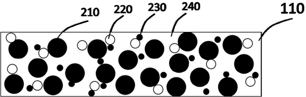
[0017] See figure 1 , figure 1 It is a schematic structural diagram of a wavelength conversion device according to Embodiment 1 of the present invention. The wavelength conversion device includes a light-emitting-reflective layer 110, and the light-emitting-reflective layer 110 includes a wavelength converting material 210, titanium oxide particles 220, aluminum oxide particles 230, and an adhesive 240. The light emitting-reflecting layer 110 not only has the function of reflecting incident light, but also has the function of emitting light after being excited.

[0018] Wherein, the wavelength conversion material is used to convert the wavelength of the excitation light from the excitation light source into the received light, and the wavelength conversion material 210 is distributed in the light emitting-reflecting layer 110 to form a light emitting center and a heat generating center. Titanium oxide particles 220 and aluminum oxide particles 230 play a reflective role and a...

Embodiment 2

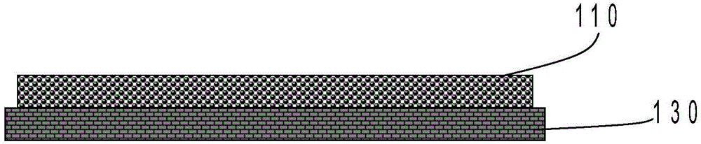
[0028] See figure 2 , figure 2 It is a schematic structural diagram of the wavelength conversion device according to the second embodiment of the present invention. Wherein the wavelength converting device includes a light emitting-reflecting layer 110 and a substrate 130 .

[0029] The light emitting-reflecting layer 110 is set according to the first embodiment, the substrate 130 is an aluminum nitride ceramic substrate, the substrate has high thermal conductivity, and has better bonding performance with the light emitting-reflecting layer 110 including aluminum oxide and titanium oxide.

[0030] In other modified embodiments, the substrate 130 may also be other ceramic substrates, such as alumina substrates, boron nitride substrates, silicon nitride substrates, silicon carbide substrates, and beryllium oxide substrates.

[0031] The substrate 130 can also be a metal substrate, such as an aluminum substrate or a copper substrate, and the metal substrate has better thermal...

Embodiment 3

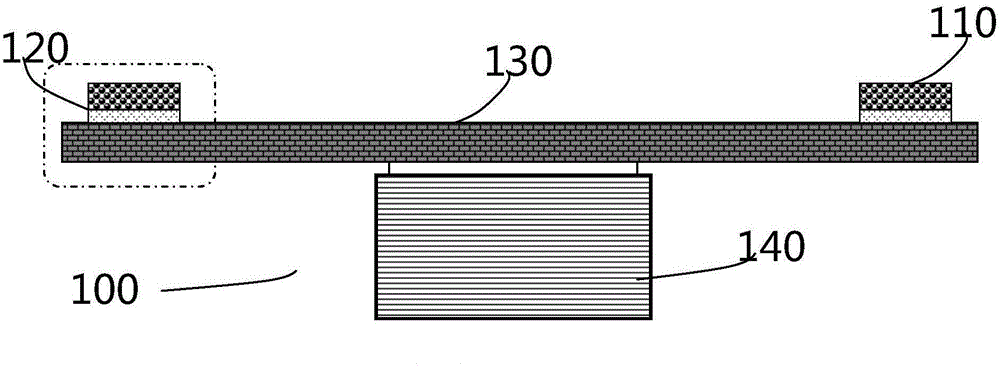
[0034] See image 3 , image 3 It is a schematic structural diagram of a three-wavelength conversion device according to an embodiment of the present invention. The wavelength conversion device includes a light-emitting-reflective layer 110 , a purely reflective layer 120 and a substrate 130 . Compared with Embodiment 2, the difference of Embodiment 3 is only that the pure reflective layer 120 located between the luminescent-reflective layer 110 and the substrate 130 is added, and the pure reflective layer 120 is used to reflect the light passing through the luminescent-reflective layer 110 go back.

[0035]The pure reflective layer 120 includes aluminum oxide, titanium oxide and an adhesive, which is the same adhesive as the luminous-reflective layer, so that the two layers can be tightly bonded without peeling due to external force or temperature changes. Phenomenon.

[0036] Alumina has excellent reflectivity for visible light, and the reflectivity of pure alumina layer...


PUM


Abstract

The invention provides a wavelength conversion device, which comprises a light emitting-reflecting layer, wherein the light emitting-reflecting layer comprises a wavelength conversion material, aluminum oxide, titanium oxide and an adhesive. Heat emission caused by propagation of exciting light in the light emitting-reflecting layer is reduced, and the density and the heat dissipation capability of the light emitting-reflecting layer are improved. Therefore, the wavelength conversion device can be suitable for an excitation light source with higher power. The invention further provides a fluorescent color wheel comprising the wavelength conversion device and a light-emitting device.

Description

technical field [0001] The invention relates to the field of wavelength conversion luminescence, in particular to a wavelength conversion device, a fluorescent color wheel and a luminous device suitable for high-power laser light sources. Background technique [0002] In the current field of lighting and projection, as people's demand for brightness gradually increases in production and life, bulbs that directly emit white light as light sources are increasingly unable to meet the lighting needs. Solid-state light sources of LED and LD are playing an increasingly important role in the field of high-brightness and high-power lighting. [0003] However, neither LED nor LD can directly provide white light. Therefore, the light source using LED or LD as the light-emitting element obtains white light by combining the three primary colors of red, green and blue light. Especially in the application of the excitation light to excite the fluorescent color wheel, the multi-color segm...

Claims


Application Information

Patent Timeline
Patent Type & Authority Applications(China)
IPC IPC(8): H01L33/46H01L33/50
CPCH01L33/501H01L33/502H01L33/507H01L33/644G02B26/008G02F1/23H01L33/46H01L33/504
Inventor 李乾陈雨叁王艳刚许颜正
Owner APPOTRONICS CORP LTD
Why Eureka
Try Eureka