Supercharge Your Innovation With Domain-Expert AI Agents!

System for holding bus residual voltage of important load

A technology for important loads and busbar residual voltage, which is applied to emergency protection circuit devices, emergency protection circuit devices, and electrical components for limiting overcurrent/overvoltage, and can solve the problem of reduced electric power, increased investment costs, and electrical equipment hazards and other problems, to achieve the effect of reducing the breaking current, increasing the system impedance, and reducing the cost

Inactive Publication Date: 2016-12-07
安徽普天电力科技有限公司
View PDF4 Cites 0 Cited by
  • Summary
  • Abstract
  • Description
  • Claims
  • Application Information

AI Technical Summary

Problems solved by technology

[0002] As we all know, when a short-circuit fault occurs in the power system, the short-circuit current is generally more than ten times the rated current, which causes great harm to electrical equipment such as transformers, generators, circuit breakers, and transmission lines. , the power load has risen sharply, and the capacity of the main transformer has also increased accordingly. The short-circuit current faced by the power grid system of various enterprises has approached and reached the maximum use limit of the load vacuum circuit breaker. The breaking capacity of the load-side vacuum circuit breaker is insufficient, and the transformer is resistant to short-circuit current impact Insufficient capacity design and other problems seriously threaten the safe operation of enterprises. Faced with today's problems, many enterprises use high-impedance transformers to limit the short-circuit current of the system, but increasing the impedance of the transformer does not finally solve the problem of current-limiting depth, and the electric power is reduced very little. It also brings active and reactive power loss, and the investment cost rises. Therefore, we propose an important load busbar residual voltage maintenance system

Method used


Image

  • System for holding bus residual voltage of important load

Examples


Embodiment Construction

[0009] In order to make the technical means, creative features, goals and effects achieved by the present invention easy to understand, the present invention will be further described below in conjunction with specific embodiments.

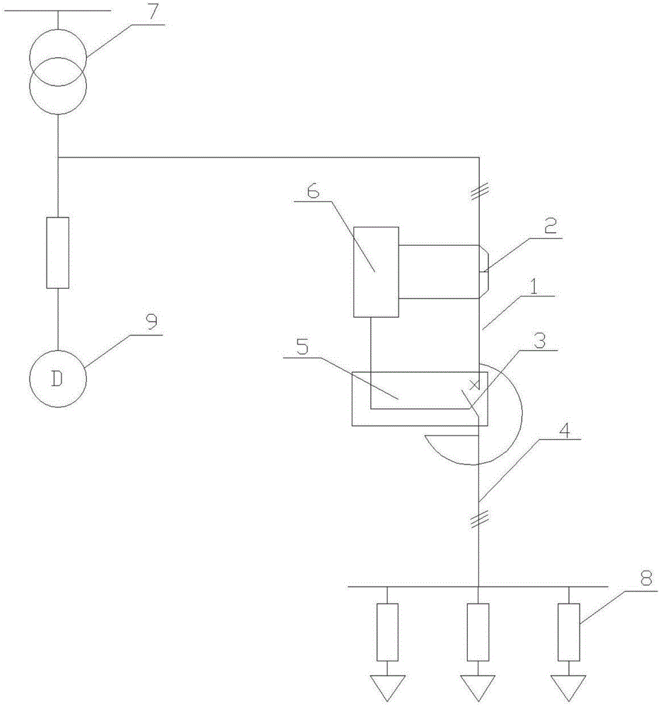
[0010] Such as figure 1 As shown, an important load busbar residual voltage maintenance system includes a deep reactor 1, and the deep reactor 1 includes a measurement and control unit 6, a Rocker coil 2 and a controller 5, and the Rocker coil 2 and the controller 5 are both Installed on the bus bar 4, the Rocker coil 2 is provided with a high-speed digital potentiometer, the controller 5 is provided with a high-speed switch 3, the signal output terminal of the high-speed digital potentiometer is connected to the signal of the high-speed switch 3 The input end is connected, the voltage output end of the bus 4 is connected with the voltage input end of the measurement and control unit 6, the signal output end of the measurement and control unit 6 i...


PUM


Abstract

The invention discloses a system for holding a bus residual voltage of an important load. The system comprises a deep reactor; the deep reactor comprises a measurement control unit, a Rogowski coil and a controller; both the Rogowski coil and the controller are mounted on a bus; a high-speed digital potentiometer is arranged in the Rogowski coil; a high-speed switch is arranged in the controller; the signal output end of the high-speed digital potentiometer is connected with the signal input end of the high-speed switch; the voltage output end of the bus is connected with the voltage input end of the measurement control unit; one end, close to the Rogowski coil, of the bus is connected in parallel with the important load and connected with a transformer; and one end, close to the high-speed switch, of the bus is connected with a load. According to the system, accurate time of a zero-crossing point of a three-phase current can be quickly and accurately predicted; through the high-speed switch, opening and closing can be accurately carried out when the current is close to zero; a short-circuit current is converted and enters the deep current-limiting reactor for limiting the short-circuit current; and the residual voltage required by the important load can be provided during instantaneous discontinuous power supply.

Description

【Technical field】 [0001] The invention relates to a current limiting device, in particular to an important load busbar residual pressure maintenance system. 【Background technique】 [0002] As we all know, when a short-circuit fault occurs in the power system, the short-circuit current is generally more than ten times the rated current, which causes great harm to electrical equipment such as transformers, generators, circuit breakers, and transmission lines. , the power load has risen sharply, and the capacity of the main transformer has also increased accordingly. The short-circuit current faced by the power grid system of various enterprises has approached and reached the maximum use limit of the load vacuum circuit breaker. The breaking capacity of the load-side vacuum circuit breaker is insufficient, and the transformer is resistant to short-circuit current impact Insufficient capacity design and other issues seriously threaten the safe operation of enterprises. Faced wit...

Claims


Application Information

Patent Timeline
Patent Type & Authority Applications(China)
IPC IPC(8): H02H9/02
CPCH02H9/02
Inventor 戴剑
Owner 安徽普天电力科技有限公司
Features
  • R&D
  • Intellectual Property
  • Life Sciences
  • Materials
  • Tech Scout
  • Unparalleled Data Quality
  • Higher Quality Content
  • 60% Fewer Hallucinations
Learn More