Integrated injection molding rotor and stepping motor applied to automatic control

An integrated, injection molding technology, applied in the control of mechanical energy, electrical components, electromechanical devices, etc., can solve the problem of the deterioration of the rotor outer diameter and the coaxiality of the rotor shaft, the higher requirements for operators and the environment, and the lack of positioning accuracy. Control requirements and other issues, to achieve the effect of small coaxiality error, improve motor efficiency, and reduce product noise

Inactive Publication Date: 2016-12-07
CHANGZHOU CHENGLI ELECTRONICS
View PDF6 Cites 6 Cited by
  • Summary
  • Abstract
  • Description
  • Claims
  • Application Information

AI Technical Summary

Problems solved by technology

[0002] At present, the rotors of the existing BY series stepping motors are mainly made of UV glue or anaerobic glue, and the metal bushing and the NdFeB magnetic ring, the metal bushing and the rotor shaft are bonded together to form a whole for production. The machining accuracy of the bushing is high, and the anti-rotation rib needs to be set in the axial direction, so the machining process is difficult to realize; in addition, the three parts that make up the rotor are all made by the gluing process, which is complicated to process and has a great impact on the level of the operator and the environment. The requirements are high, and the flow properties of the glue will affect the bonding effect and bonding accuracy, which will cause the defects of weak bonding between the parts and poor coaxiality between the outer diameter of the rotor and the rotor shaft after bonding and curing. If the overflowing glue is not cleaned up in time during the bonding process, there will be flashes on the cured rotor, and the flashes will easily be brought into the motor to form garbage, which will block the rotation of the rotor, and the overflowing glue will easily remain on the rotor shaft On the other hand, the resistance between the motor shaft and the bearing in normal operation becomes larger, which affects the pull-out torque, and causes the motor to be stuck in serious cases; these technical problems are common in motor rotor products that are bonded with glue, and there is no such problem until now. A more reasonable way to solve this technical problem has resulted in BY series stepper motors failing to meet the precise positioning accuracy control requirements in demanding patented equipment drives, which limits the application of this type of product in the field of automation control

Method used


Image

  • Integrated injection molding rotor and stepping motor applied to automatic control
  • Integrated injection molding rotor and stepping motor applied to automatic control
  • Integrated injection molding rotor and stepping motor applied to automatic control

Examples


Embodiment Construction

[0040] In order to make the content of the present invention more clearly understood, the present invention will be further described in detail below based on specific embodiments and in conjunction with the accompanying drawings.

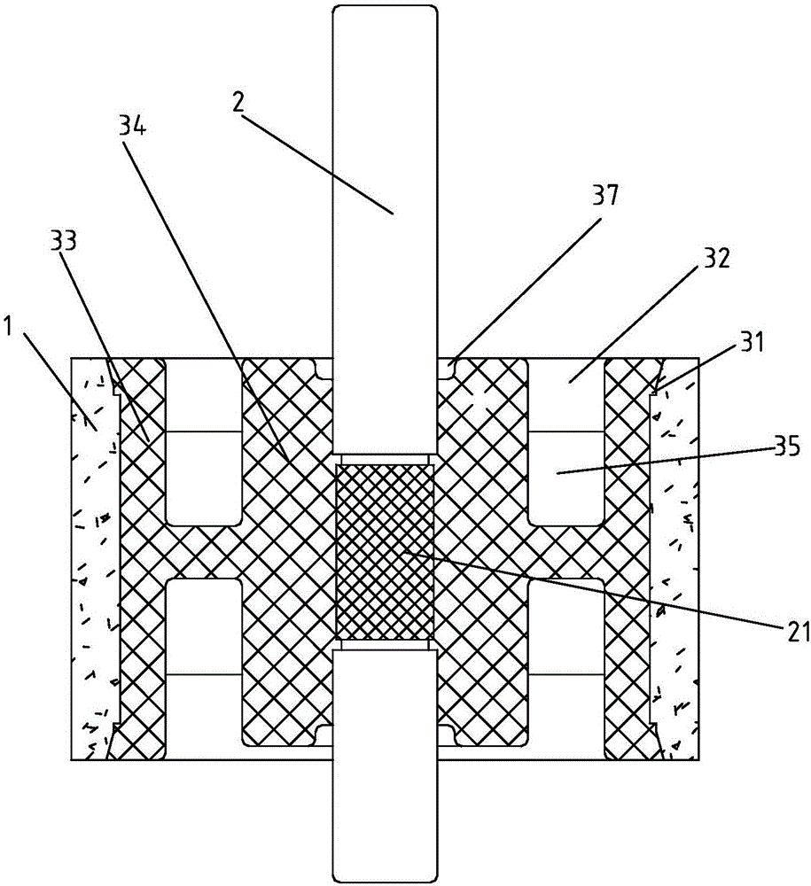
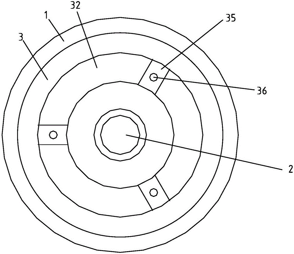
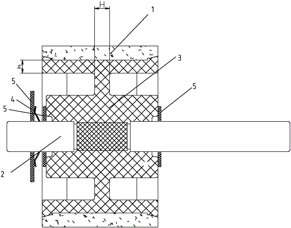
[0041] Such as Figure 1~5 As shown, a one-piece injection molded rotor, which includes:

[0042] magnetic ring 1;

[0043] rotary axis 2;

[0044] Injection molded body 3, said injection molded body 3 is arranged between magnetic ring 1 and rotary shaft 2, so that said injection molded body 3 makes rotary shaft 2 and magnetic ring 1 into one, and said magnetic ring 1 and injection molded body 3 There is a magnetic ring limiting mechanism that locks the relative position between the magnetic ring 1 and the injection molding body 3 so as to increase the bonding fastness between the magnetic ring 1 and the injection molding body 3; this embodiment introduces a magnetic ring limiting mechanism The specific structure is as follows:

[0045] The mag...


PUM


Abstract

The invention discloses an integrated injection molding rotor and a stepping motor applied to automatic control. The integrated injection molding rotor comprises a magnet ring, a rotating shaft, an injection molding body arranged between the magnet ring and the rotating shaft to facilitate that the injection molding body makes the rotating shaft and the magnet ring into a whole. The rotating shaft and the magnet ring are made into the whole through injection molding, the rotor manufacturing precision is greatly improved by arranging a speed-reducing grooved cavity and a special gate position, the machining process is simple, the made rotor assembly is small in coaxiality error, stable in quality and high in reliability, the positioning accuracy of the BY series stepping motor is remarkably improved, product noise is reduced, torque pulsations are decreased, the motor efficiency is improved, and the BY series stepping motor can be widely applied in special working and medical treatment automation equipment driving occasions having higher requirements and the field of automatic control.

Description

technical field [0001] The invention relates to an integral injection molded rotor and a stepping motor applied to automatic control, belonging to the technical field of motors. Background technique [0002] At present, the rotors of the existing BY series stepping motors are mainly made of UV glue or anaerobic glue, and the metal bushing and the NdFeB magnetic ring, the metal bushing and the rotor shaft are bonded together to form a whole for production. The machining accuracy of the bushing is high, and the anti-rotation rib needs to be set in the axial direction, so the machining process is difficult to realize; in addition, the three parts that make up the rotor are all made by the gluing process, which is complicated to process and has a great impact on the level of the operator and the environment. The requirements are high, and the flow properties of the glue will affect the bonding effect and bonding accuracy, which will cause the defects of weak bonding between the ...

Claims


Application Information

Patent Timeline
Patent Type & Authority Applications(China)
IPC IPC(8): H02K37/10H02K5/24H02K7/00
CPCH02K37/10H02K5/24H02K7/003H02K2213/03
Inventor 赵殿合党红关
Owner CHANGZHOU CHENGLI ELECTRONICS
Why Eureka
Try Eureka