Sensor-free charging control method of magnetic levitation energy storage flywheel

A charging control method, energy storage flywheel technology, applied in motor generator control, electronic commutation motor control, control system and other directions

Inactive Publication Date: 2016-12-07
BEIJING HONGHUI INT ENERGY TECH DEV CO LTD
View PDF4 Cites 13 Cited by
  • Summary
  • Abstract
  • Description
  • Claims
  • Application Information

AI Technical Summary

Problems solved by technology

These methods are based on the motor current model to estimate the angular position, which is suitable for the operation of the motor at a certain speed, but when the motor is started, the current is zero, or when the motor is switching between charging and discharging, the current has a zero crossing point. The current model has no output for angular position estimation using the method described above

Method used


Image

  • Sensor-free charging control method of magnetic levitation energy storage flywheel
  • Sensor-free charging control method of magnetic levitation energy storage flywheel
  • Sensor-free charging control method of magnetic levitation energy storage flywheel

Examples


Embodiment 1

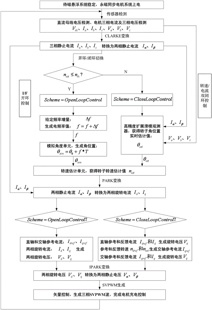
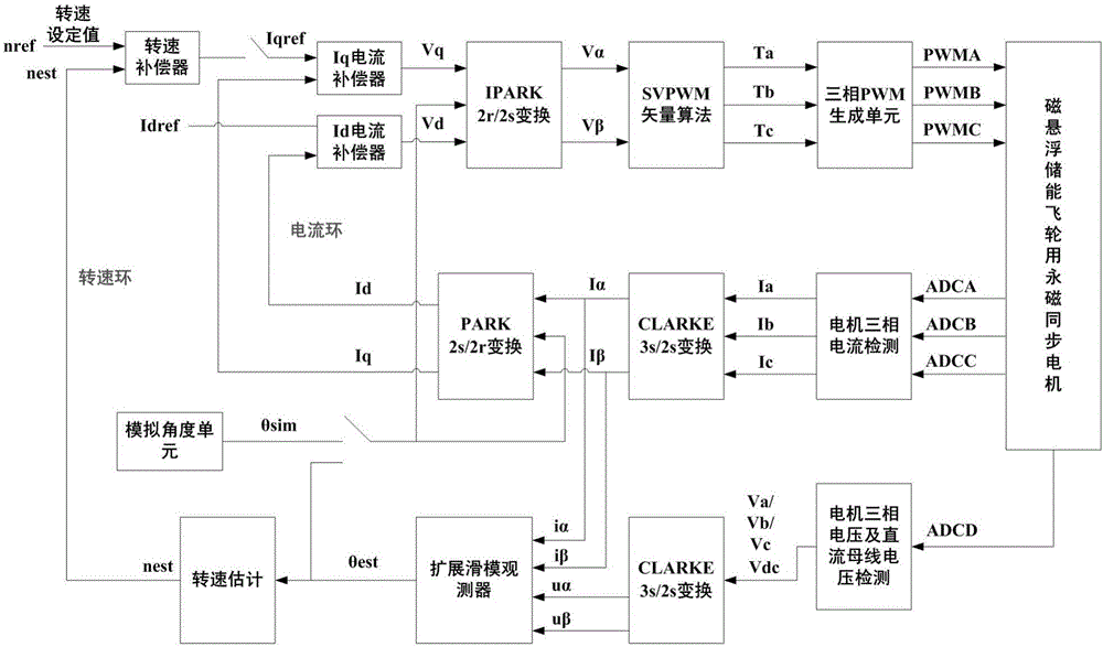
[0026] A sensorless charging control method for a magnetic levitation energy storage flywheel. The control method includes ten steps. The first step is to control the stable operation of the magnetic levitation system, and then the permanent magnet synchronous motor used to drive the flywheel to rotate is powered on; the second step is installed at the input end of the motor. The Hall current sensor respectively measures the three-phase current I of the motor a , I b , I c , the voltage sensor measures the motor three-phase voltage V a , V b , V c and DC bus voltage Vdc ; In the third step, the three-phase quiescent current I obtained in the second step a , I b , I c Input to the three-phase static to two-phase static conversion CLARKE module to generate a two-phase static current I α , I β ; The fourth step is based on the speed estimation value θ est with the set threshold θ th The relationship between open-loop and closed-loop control switching; the fifth step is ...

Embodiment 2

[0028] A sensorless charging control method for a magnetic levitation energy storage flywheel described in Embodiment 1, the fourth step is based on the estimated rotational speed θ est with the set threshold θ th The relationship between open-loop and closed-loop control switching is when θ est ≤θ th , adopt constant current frequency ratio I / F open-loop control and set the variable Scheme=OpenLoopControl; when θ est th , using speed / current double closed-loop control and setting variable Scheme=CloseLoopControl; where OpenLoopControl=0, CloseLoopControl=1.

Embodiment 3

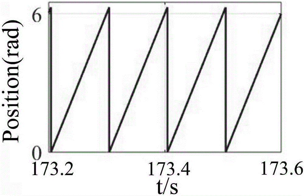
[0030] In the sensorless charging control method of a magnetic levitation energy storage flywheel described in Embodiment 1, the fifth step of obtaining the angular position of the rotor is if Scheme=OpenLoopControl, then a frequency increment Δf is given to generate an electric frequency value f=f+ Δf, input to the analog angle unit to generate the angular position θ=θo+f*T, where θo is the initial angular position, and T is the sampling period; if Scheme=CloseLoopControl, the Va, Vb, Vc obtained in the second step and the third I α , I β Input to the high-precision extended sliding mode observer to obtain the estimated rotor angular position θ est .


PUM


Abstract

The invention discloses a sensor-free charging control method of a magnetic levitation energy storage flywheel. The control method comprises the steps of 1, controlling a magnetic levitation system to stably work; 2, measuring three-phase static currents I, I and I<c> of a motor by a Hall current sensor mounted at the input end of the motor; 3, inputting the three-phase static currents I, I and I<c> to a three-phase static to two-phase static conversion CLARKE module; 4, performing open loop and closed loop control switching according to a relationship between a rotating speed estimation value theta<est>and a set threshold theta; 5, obtaining an angle position of a rotor; 6, inputting an angle position simulation value theta<sim> and the estimation value theta<est> to a rotating speed estimation unit so as to obtain a rotating speed estimation value nest of the rotor; 7, inputting I<alpha>, I<beta> and the angle position of the rotor to a two-phase static to two-phase rotating conversion PARK module; 8, performing closed loop feedback control; 9, inputting V<d> and V<q> to a two-phase static to two-phase rotating conversion IPARK module; and 10, performing vector control according to V<alpha> and V<beta> obtained in the step 9. The method is used for sensor-free charging control of the magnetic levitation energy storage flywheel.

Description

Technical field: [0001] The invention relates to a sensorless charging control method for a magnetic suspension energy storage flywheel. Background technique: [0002] Magnetic levitation flywheel energy storage technology is a new and advanced mechanical energy storage method, which has the advantages of rapid charging and discharging, high power, long life and little environmental pollution. better application. The permanent magnet synchronous motor has the advantages of simple structure, small size, high power factor, high power density, and low moment of inertia. It is an ideal choice for driving the flywheel to complete the charging and discharging process. [0003] The existing permanent magnet synchronous motor control methods are mainly divided into two categories: sensor control and sensorless control. Among them, sensor control mainly uses photoelectric encoders, resolvers, etc. to measure the actual position of the rotor flux linkage, and at the same time uses H...

Claims


Application Information

Patent Timeline
Patent Type & Authority Applications(China)
IPC IPC(8): H02P21/22H02P21/13
CPCH02P21/13
Inventor 李树胜王志强刘海财郭巍齐聪睿
Owner BEIJING HONGHUI INT ENERGY TECH DEV CO LTD
Why Eureka
Try Eureka