Oxygenation device for aquaculture pond driven by circulating water
A technology for breeding ponds and circulating water, applied in fish farming, applications, animal husbandry, etc., can solve the problems of high operating costs, waste of water resources, death, etc., and achieve the effect of reducing the energy consumption of aquaculture
- Summary
- Abstract
- Description
- Claims
- Application Information
AI Technical Summary
Problems solved by technology
Method used
Image
Examples
Embodiment 1
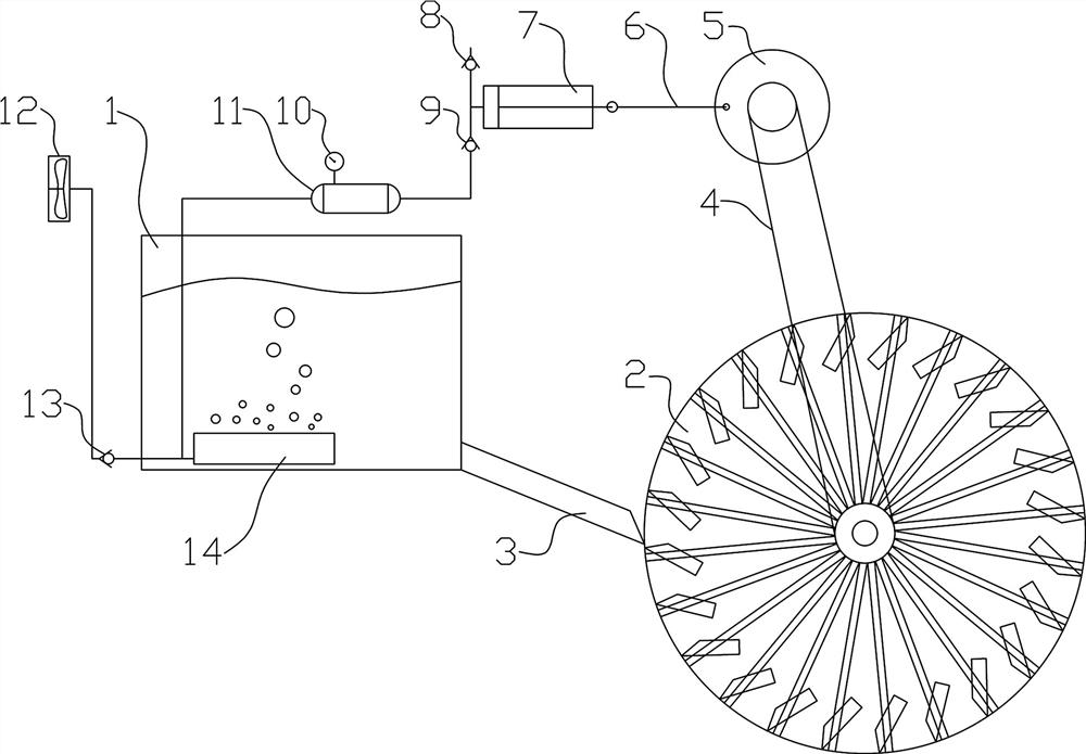
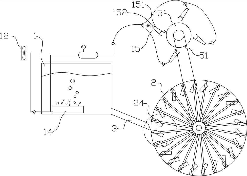
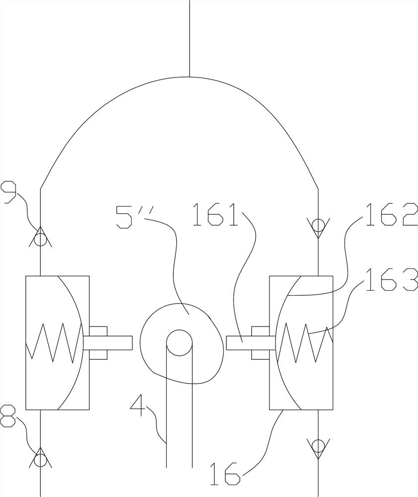
[0027] like Figure 1~2 Among them, a circulating water-driven aquaculture pond oxygenation device, the hydraulic device 2 arranged in the drainage channel 3 is connected to the driving mechanism through the transmission mechanism 4, the driving mechanism is connected to the air pump and drives the air pump to act, and the air pump passes through the exhaust one-way valve 9 It is connected with the microporous aeration device 14 located in the culture pond 1 . With this structure, the water flow in the drainage channel 3 drives the hydraulic device 2 to rotate so as to drive the driving mechanism to move, and the driving mechanism drives the air pump to move, thereby sending the gas into the microporous aeration device 14 after being pressurized. Gas therefore needs to be provided with an exhaust one-way valve 9 that can only be exhausted but not inhaled. The microporous aeration device 14 is a tube with micropores, or a cavity with micropores on the top. Compressed air is di...
Embodiment 2
[0029] On the basis of Example 1, the preferred scheme is as figure 1 , 2 Among them, the hydraulic device 2 is a waterwheel, and the waterwheel is provided with a water tank 24 arranged obliquely, and the water tanks 24 are evenly distributed along the circumference of the waterwheel. With this structure, the position of the water wheel at the middle elevation from top to bottom faces the drainage channel 3, and the gravity difference formed by receiving water from the water tank pushes the water wheel to rotate, and the water tank runs to the bottom of the water wheel, and the water is discharged from the water tank to reduce weight. In this example, it is preferable to use a water tank with a rectangular cross section, the width of which is the same as that of the drainage channel 3, so as to increase the torque of the waterwheel. Thereby it is convenient to adopt the transmission mechanism of increasing speed. The transmission mechanism in this example is a chain transm...
Embodiment 3
[0031] On the basis of Example 1, the preferred scheme is as Figure 4 Among them, the hydraulic device 2 is a belt waterwheel 2', at least two pulleys 21 are arranged along the drainage channel 3, the belt 22 goes around the two pulleys 21, and water buckets 23 or buckets are evenly distributed on the belt 22. Paddle board, water bucket 23 or paddle board run to below belt wheel 21 when, be positioned at the water of drainage channel 3. The waterwheel takes up a lot of space, while the belt waterwheel 2' in this example has the advantage of taking up little space. Moreover, the hydraulic utilization rate of the water flow in the drainage channel 3 is high.
PUM
 Abstract
Description
Claims
Application Information
 - R&D
- Intellectual Property
- Life Sciences
- Materials
- Tech Scout
- Unparalleled Data Quality
- Higher Quality Content
- 60% Fewer Hallucinations
Browse by: Latest US Patents, China's latest patents, Technical Efficacy Thesaurus, Application Domain, Technology Topic, Popular Technical Reports.
© 2025 PatSnap. All rights reserved.Legal|Privacy policy|Modern Slavery Act Transparency Statement|Sitemap|About US| Contact US: help@patsnap.com


