Kitchen automatic fire extinguishing device achieving zone control

A technology of automatic fire extinguishing and partition control, which is applied in fire rescue and other fields, and can solve the problems of large mechanical drive force, inaccuracy, and easy breakage of fuses, and achieve the effect of rapid signal transmission, reduced installation costs, and not easy to break

Pending Publication Date: 2016-12-14
陕西卫仕厨房灭火设备有限公司
View PDF6 Cites 8 Cited by
  • Summary
  • Abstract
  • Description
  • Claims
  • Application Information

AI Technical Summary

Problems solved by technology

[0004] 1. The pulleys used in the installation process cannot turn too much, the distance cannot be too large, and it cannot be installed across spaces and regions. For a kitchen with a large area or a kitchen divided into multiple different areas, multiple sets of equipment need to be installed, and the cost is too high;
[0005] 2. When a fire occurs, the fire extinguishing equipment as a whole starts to extinguish the fire. For a fire in a small area, all the nozzles will be turned on to extinguish the fire. The fire extinguishing is not targeted and accurate, resulting in waste of fire extinguishing materials, and for areas where there is no fire It also caused a large amount of food loss;
[0006] 3. The tensile force of the mechanical driver is large, and the fuse is easily broken due to too much force. Once the fuse breaks due to external force, it will send a fire signal to the equipment, resulting in early spraying and wrong spraying, and the signal transmission speed of the mechanical drive is slow.

Method used


Image

  • Kitchen automatic fire extinguishing device achieving zone control
  • Kitchen automatic fire extinguishing device achieving zone control
  • Kitchen automatic fire extinguishing device achieving zone control

Examples


Embodiment 1

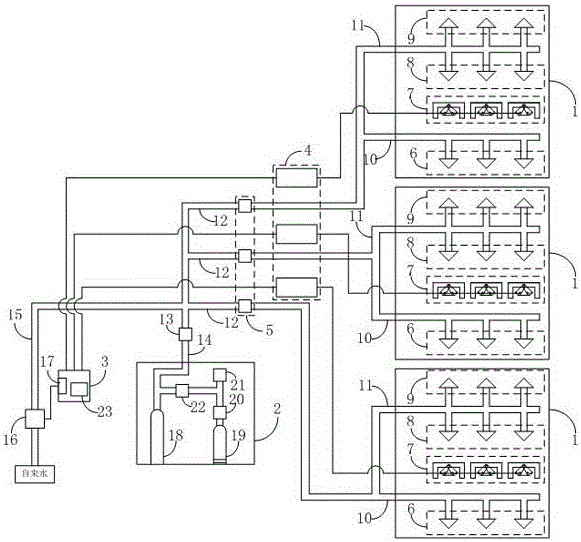
[0031] Such as figure 1 As shown, a schematic diagram of the system structure of a kitchen automatic fire extinguishing device with partition control according to the present invention, including a plurality of fire extinguishing mechanisms 1, a fire extinguishing box 2 and a control box 3, wherein it also includes a plurality of fire signal transmission devices 4, fire signal transmission devices The number of 4 is the same as that of the fire extinguishing mechanism 1, the input end of the fire signal transmission device 4 is connected to the fire extinguishing mechanism 1, and the output end is connected to the control box 3;

[0032] The fire extinguishing mechanism 1 includes a first fire extinguishing pipe 10 and a plurality of temperature sensors 7 arranged above the stove, and a second fire extinguishing pipe 11 arranged in the flue. The first fire extinguishing pipe 10 is provided with a plurality of The first nozzle 6 for fire extinguishing, the second fire extinguis...

Embodiment 2

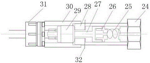
[0038] Such as figure 2 As shown, the structure diagram of the fire signal transmission device in a kitchen automatic fire extinguishing device with partition control according to the present invention, the fire signal transmission device 4 includes a fixing part 24, a spring compression part 28, a switch fixing part 30 and a bushing 31 connected in sequence , the spring compression part 28 is internally provided with a switch starter and a spring 25, the switch starter includes a wire fixing part 26 and a driving part 27, the spring 25 is located between the wire fixing part 26 and the fixing part 24 and the wire fixing part 26 and the fixing part Parts 24 are provided with through holes, and spring compression parts 28 are provided with small holes, which are provided with inserted safety pins 32, and switch fixing parts 30 are internally provided with switches 29; fixing parts 24, spring compression parts 28, switches Both the fixing part 30 and the sleeve pipe 31 are conn...

Embodiment 3

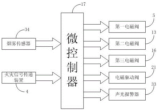
[0041] The fire extinguishing box 2 is provided with a medicine bottle 18 and a nitrogen tank 19, the mouth of the nitrogen tank 19 is connected with a bottle head valve 20, and the bottle head valve 20 is connected with an electromagnetic driver 21, and the medicine bottle 18 and the nitrogen tank 19 are connected with a reducing valve. Pressure valve 22, medicament bottle 18 is communicated with described fire extinguishing main pipeline 14 by second electromagnetic valve 13, and electromagnetic driver 21 is connected with output end of microcontroller 17; Control box 3 also comprises audible and visual alarm 33, audible and visual alarm 33 Connect with microcontroller 17 output terminals; Smoke sensor 34 is arranged in the flue, and smoke sensor 34 is connected with the input terminal of microcontroller 17, as image 3 As shown, the circuit principle block diagram of a kind of partition control kitchen automatic fire extinguishing device of the present invention.

[0042] D...


PUM


Abstract

The invention belongs to fire extinguishing equipment, and particularly relates to a kitchen automatic fire extinguishing device achieving zone control. The kitchen automatic fire extinguishing device comprises a plurality of fire extinguishing mechanisms, a fire extinguishing box and a control box. A plurality of fire signal transmission devices are further included. The number of the fire signal transmission devices is the same as that of the fire extinguishing mechanisms. The input ends of the fire signal transmission devices are connected with the fire extinguishing mechanisms, and the output ends of the fire signal transmission devices are connected with the control box. According to the kitchen automatic fire extinguishing device, under the conditions that the area of a kitchen is too large, or the kitchen is divided into a plurality of zones, and even kitchens are distributed in different rooms, one corresponding fire signal transmission device only needs to be mounted on each fire extinguishing mechanism, multiple units of equipment can be jointly connected to the control box and the fire extinguishing box, multiple sets of equipment do not need to be mounted, and mounting cost is reduced; and zone control can be carried out on the different zones, targeted fire extinguishing can be carried out when a fire happens, and fire extinguishing materials and kitchen food material losses are greatly reduced.

Description

technical field [0001] The invention belongs to fire extinguishing equipment, and in particular relates to a kitchen automatic fire extinguishing device with zone control. Background technique [0002] At present, there are canteens in public buildings such as hotels, guesthouses, troops, hospitals, schools, enterprises and institutions, and gas stoves are usually installed on the canteen stoves. If the gas stove is out of control, it will cause the cooking oil in the pot It ignites quickly in a very short period of time, and when the fire expands, it will further cause the grease in the fume hood and exhaust pipe to ignite, resulting in a sky-high fire that is difficult to put out. And smoke exhaust pipes have become the key protection objects in the canteen. [0003] The fire extinguishing device currently used in the field of domestic and foreign kitchen fire extinguishing devices is a mechanical drive, using a wire rope to pull the fuse on the temperature sensor through...

Claims


Application Information

Patent Timeline
Patent Type & Authority Applications(China)
IPC IPC(8): A62C3/00A62C35/58A62C37/00
CPCA62C3/006A62C35/58A62C37/04
Inventor 李红梅
Owner 陕西卫仕厨房灭火设备有限公司
Why Eureka
Try Eureka