Ultrasonic mixing vacuum stirring tank for natural ester insulation oil

A vacuum stirring and ultrasonic technology, which is applied to mixers, mixers, and mixer accessories with rotating stirring devices, can solve problems such as the performance degradation of natural ester insulating oil, and achieve the purpose of improving service life, preventing damage and improving stirring efficiency. Effect

Active Publication Date: 2016-12-14
STATE GRID HENAN ELECTRIC POWER ELECTRIC POWER SCI RES INST +1
View PDF14 Cites 6 Cited by
  • Summary
  • Abstract
  • Description
  • Claims
  • Application Information

AI Technical Summary

Problems solved by technology

[0006] In view of this, the purpose of the present invention is to address the deficiencies in the prior art, to provide an ultrasonic mixing vacuum mixing tank for natural ester insulating oil, by setting a vacuum pumping valve, a one-way feed valve, a one-way discharge valve And the air seal device can maintain the vacuum environment in the tank well, effectively avoiding the performance degradation of natural ester insulating oil caused by moisture and oxygen in the air during stirring

Method used


Image

  • Ultrasonic mixing vacuum stirring tank for natural ester insulation oil
  • Ultrasonic mixing vacuum stirring tank for natural ester insulation oil
  • Ultrasonic mixing vacuum stirring tank for natural ester insulation oil

Examples


Embodiment 1

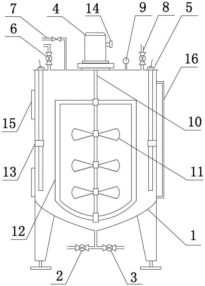
[0027] Such as figure 1 As shown, the present invention includes tank body 1, one-way feed valve 2, one-way discharge valve 3, stirring paddle, frequency conversion motor 4, ultrasonic vibrating rod 5, vacuum pumping valve 6, pressure relief valve 7, additive feeding The valve 8 and the vacuum gauge 9; the one-way feed valve 2 and the one-way discharge valve 3 are sealed and installed at the bottom of the tank body 1; the stirring paddle is located in the tank body 1, including the rotating shaft 10, the inclined blade paddle 11 and the frame paddle 12 , three inclined-blade paddles 11 are fixed in the middle of the rotating shaft 10, the upper frame of the frame-type paddle 12 is located above the uppermost pitched-blade paddle 11, and the lower frame of the frame-type paddle 12 is located below the lowermost pitched-blade paddle 11 The frequency conversion motor 4 is installed above the tank body, and the rotating shaft 10 extends out of the tank body and is sealed and rotat...

Embodiment 2

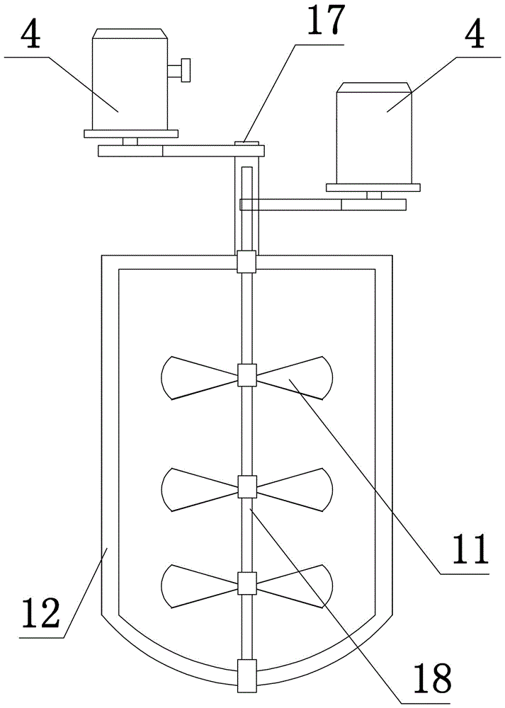
[0030] The present invention includes a tank body 1, a one-way feed valve 2, a one-way discharge valve 3, a stirring paddle, a frequency conversion motor 4, an ultrasonic vibrating rod 5, a vacuum pumping valve 6, a pressure relief valve 7, an additive feed valve 8 and The vacuum gauge 9; the one-way feed valve 2 and the one-way discharge valve 3 are sealed and installed at the bottom of the tank body 1; Including rotating shaft 1 17 and rotating shaft 2 18 which are sealed and socketed, the frame paddle 12 is fixedly connected with rotating shaft 1 17, three inclined blade type paddles 11 are fixedly connected with rotating shaft 2 18, and the upper frame of frame type paddle 12 is located at the uppermost inclined Above the blade type paddle 11, the lower frame of the frame type paddle 12 is located below the lowermost inclined blade type paddle 11; two frequency conversion motors 4 are installed above the tank body, and the upper ends of the first rotating shaft 17 and the s...

Embodiment 3

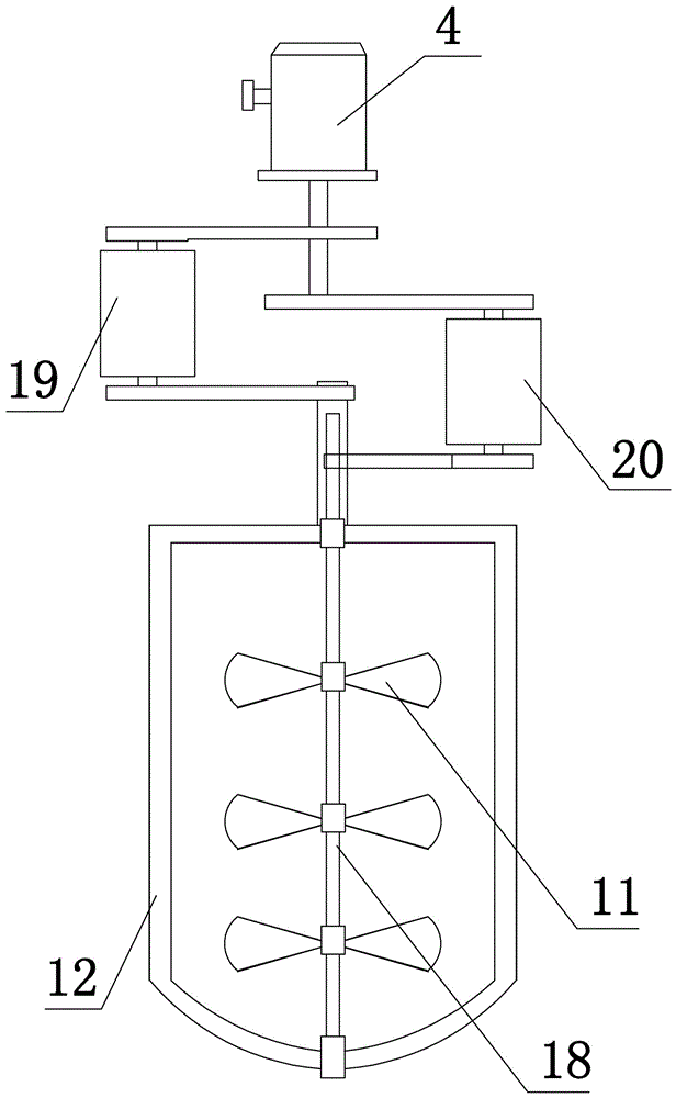
[0033] The structure of this embodiment is basically the same as that of Embodiment 2, the difference is: as image 3 As shown, the frequency conversion motor 4 is one, and a speed reducer 19 can be installed between the frequency conversion motor 4 and the rotating shaft 17, and a speed reducer 20 is installed between the frequency conversion motor 4 and the rotating shaft 2 18, and the speed reducer 19 and the speed reducer The reduction ratio of device two 20 is different, so as to realize the adjustment of the different rotating speeds of the inclined blade type paddle 11 and the frame type paddle 12; as Figure 4 As shown, it is also possible to install a reversing device 21 between the variable frequency motor 4 and the rotating shaft 17, and the reversing device 21 can adopt the steering mechanism or equipment in the prior art to realize the transmission so that the rotation direction of the rotating shaft 17 is the same as that of the rotating shaft 2 18. The direction...


PUM


Abstract

The invention discloses an ultrasonic mixing vacuum stirring tank for natural ester insulation oil. The ultrasonic mixing vacuum stirring tank comprises a tank body, a one-way material inlet valve, a one-way material outlet valve, a stirring paddle, a variable-frequency motor, an ultrasonic vibration bar, a vacuum air suction valve, a pressure relief valve, an additive inlet valve and a vacuum gauge, wherein the one-way material inlet valve and the one-way material outlet valve are respectively arranged at the bottom part of the tank body in a sealing way; the upper end of the stirring paddle extends out of the tank body, and is rotationally connected with the tank body in a sealing away, and the top end of the stirring paddle is connected with the output end of the variable-frequency motor; one end of the ultrasonic vibration bar is fixedly arranged at the top part of the tank body, and a clamping hoop is arranged at the inside wall of the tank body, and is used for fixing the ultrasonic vibration bar. The ultrasonic mixing vacuum stirring tank has the advantage that by arranging the vacuum air suction device, the one-way material inlet valve, the one-way material outlet valve and an air seal device, the vacuum environment in the tank body is well maintained, and the problem of property degrading caused by moisture and oxygen in air due to the stirring of natural ester insulation oil is effectively solved.

Description

technical field [0001] The invention belongs to the technical field of stirring equipment, and in particular relates to an ultrasonic mixing vacuum stirring tank for natural ester insulating oil. Background technique [0002] Stirring tank is a commonly used equipment in the production of insulating oil. Generally, mechanical stirring is used. It is mainly used to stir the insulating oil with additives in various forms to achieve the purpose of mixing evenly. However, most conventional mixing tanks are atmospheric pressure tanks. Natural ester insulating oil has the characteristics of strong hygroscopicity and poor oxidation resistance. Therefore, when heated and stirred at normal pressure, natural ester insulating oil will absorb moisture in the air and oxidize with oxygen in the air, thereby forming natural ester insulating oil The physical, chemical and electrical insulation performance of the natural ester insulating oil is reduced, so the vacuum stirring tank is used i...

Claims


Application Information

Patent Timeline
Patent Type & Authority Applications(China)
IPC IPC(8): B01F13/10B01F11/00B01F13/06B01F7/00B01F15/00
CPCB01F31/83B01F31/85B01F31/87B01F33/822B01F2101/40Y02P70/10
Inventor 杨涛寇晓适王吉付刚王天王震宇蒲兵舰马德英付海金马伦潘静鸽李祺张慧
Owner STATE GRID HENAN ELECTRIC POWER ELECTRIC POWER SCI RES INST
Why Eureka
Try Eureka