In-situ soil remediation device utilizing solar energy and construction method for same

A soil remediation and solar energy technology, which is applied in the field of in-situ soil remediation devices, can solve the problems of high operating costs, high energy consumption costs, and high reagent costs, and achieve low manpower and material costs, small on-site labor, and simple construction methods Effect

Active Publication Date: 2016-12-14
TSINGHUA UNIV
View PDF11 Cites 5 Cited by
  • Summary
  • Abstract
  • Description
  • Claims
  • Application Information

AI Technical Summary

Problems solved by technology

[0010] 1. Using the most common ex-situ restoration method, the polluted soil needs to be excavated and then processed. This method generally has high construction costs
[0011] 2. For the ectopic repair method, it is difficult to manage the excavated contaminated soil, which is likely to cause secondary pollution
[0012] 3. Ectopic repair methods generally involve chemical and biological treatments, and the cost of reagents is high
Some treatment methods use heating, and the corresponding energy costs are high
In the above reference, solar energy is used for ex situ heating to repair, but the energy consumption required for thermal desorption is very high. If solar energy is used to achieve this purpose, very large area solar panels are required, and the cost will be very high
[0013] 4. Using the in-situ repair method can save the cost of excavation construction, but most of the in-situ repair methods require continuous power supply or other energy input, so the operating cost is relatively high
[0014] 5. Most of the in-situ repair methods require the construction of some permanent facilities, such as the cement floor for operation, installed pumps and pipelines, etc., and the corresponding costs are relatively high
[0015] 6. Most of the in-situ soil remediation methods require drilling and construction of extraction wells, which are very costly

Method used


Image

  • In-situ soil remediation device utilizing solar energy and construction method for same
  • In-situ soil remediation device utilizing solar energy and construction method for same
  • In-situ soil remediation device utilizing solar energy and construction method for same

Examples


Embodiment Construction

[0061] The present invention will be further described in detail below in conjunction with specific embodiments, which are explanations of the present invention rather than limitations.

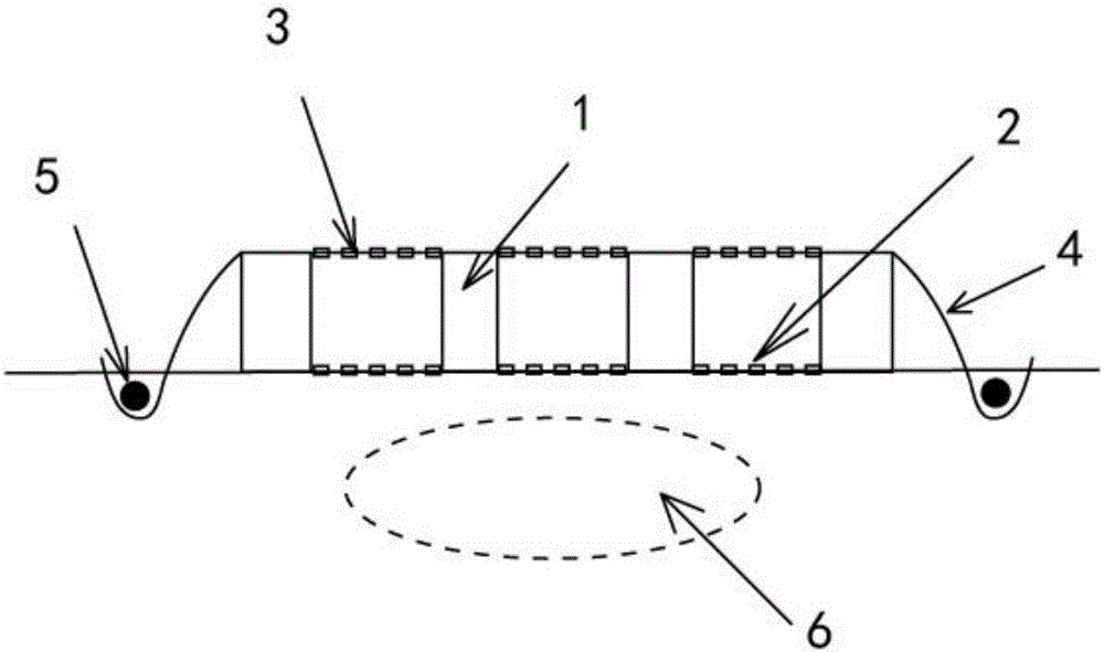
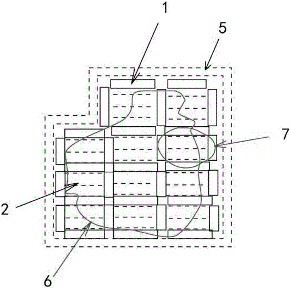
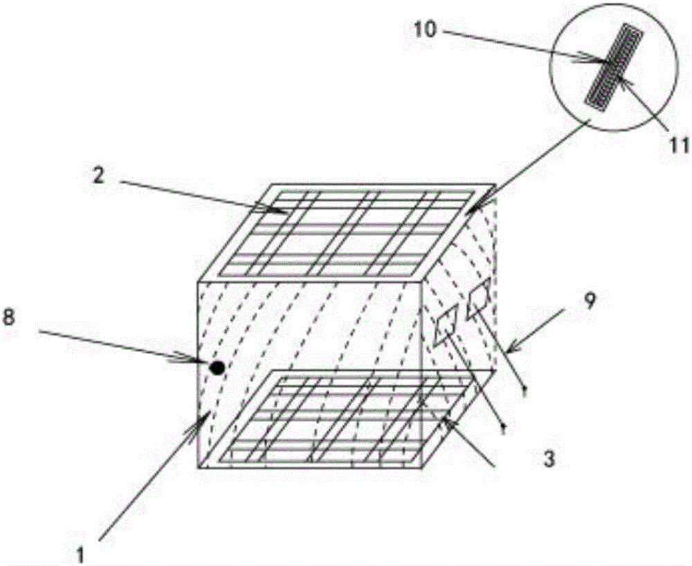
[0062] An in-situ soil remediation device using solar energy, which is composed of a plurality of independent installation units 7 spliced ​​together, and the part of the whole device near the ground is black; the independent installation unit 7 includes an enclosed inflatable cavity 1, and the inflatable cavity 1 is connected to the ground Anchor connection, the bottom of the inflatable cavity 1 is connected to the black plastic cloth 2 laid on the ground with grid openings, and the top is connected to the transparent plastic cloth 3 with grid openings;

[0063] The two adjacent independent installation units 7 share the inflatable cavity 1, and the outermost inflatable cavity is also provided with an anchoring plastic cloth 4 facing the outside, and one end of the anchoring plastic cloth 4 i...


PUM


Abstract

The invention discloses an in-situ soil remediation device utilizing solar energy and a construction method for the same. The device is spliced by multiple separate assembly units; the part, close to the ground, of the whole device is black; each separate assembly unit comprises enclosed inflation cavities; each inflation cavity is in anchoring connection with the ground; the bottom of each inflation cavity is connected with a black plastic cloth which is laid on the ground and is provided with a grid opening; and the top of each inflation cavity is connected with a transparent plastic cloth which is laid on the ground and is provided with a grind opening. The in-situ soil remediation device can absorb solar energy to the greatest extent, and can heat air in the device. Based on a flue effect in the construction and the Bernoulli's effect formed by horizontal air streams on the top end of the construction, upward air streams are formed in the construction, and upward air streams in shallow soil are driven, so that alternate nonequilibrium state transportation of organic pollutants in the soil is caused, and diffusion of the organic pollutants to soil air is caused; and the solar energy and barometric pressure energy are fully utilized, so that the pollutants in the soil and shallow underground water are effectively removed.

Description

technical field [0001] The invention belongs to the technical field of soil restoration, and relates to an in-situ soil restoration device utilizing solar energy and a construction method thereof. Background technique [0002] In recent years, with the rapid development of society and economy, and the continuous progress of my country's industrial and agricultural technology, environmental problems have become increasingly prominent. Soil pollution in our country is becoming more and more serious, and the pollution of organic matter is particularly serious and relatively harmful. Organic pollutants in soil can cause numerous hazards, including the inhibition of animals, plants and microorganisms in the soil ecosystem, the harmful effects on human health, and so on. When the human body directly contacts the polluted soil, it can cause adverse reactions in sensory and physiological functions, reduce the body's resistance, and be accompanied by an increase in the incidence and...

Claims


Application Information

Patent Timeline
Patent Type & Authority Applications(China)
IPC IPC(8): B09C1/00
CPCB09C1/00B09C2101/00
Inventor 侯德义李广贺张旭张芳李淼
Owner TSINGHUA UNIV
Why Eureka
Try Eureka