Automatic chip discharging device for numerical control machine tool

A CNC machine tool and automatic discharge technology, which is used in metal processing machinery parts, maintenance and safety accessories, metal processing equipment, etc., can solve the problem that the effect of chip removal is not very satisfactory, affects the health of the recipient, and the waste is not collected cleanly, etc. problems, to achieve the effect of preventing heat damage, preventing heat, and increasing attractiveness

Inactive Publication Date: 2016-12-14
张民胜
View PDF5 Cites 4 Cited by
  • Summary
  • Abstract
  • Description
  • Claims
  • Application Information

AI Technical Summary

Problems solved by technology

[0002] The main function of the automatic chip removal device for CNC machine tools is to collect various metal or non-metallic waste chips generated by the CNC machine tool during work, and transfer the waste chips to the collection bin for collection for unified processing. The usual chip removal device There are scraper type, chain plate type and spiral type, etc. The structure of the traditional chip removal method is relatively simple, and the effect of chip removal is not very ideal, and there will still be waste chips that are not collected, so that there will be waste chips in the environment of the staff, which is easy to Inhaled into the body by the user, thereby affecting the health of the user

Method used


Image

  • Automatic chip discharging device for numerical control machine tool
  • Automatic chip discharging device for numerical control machine tool

Examples


Embodiment Construction

[0014] The following will clearly and completely describe the technical solutions in the embodiments of the present invention with reference to the accompanying drawings in the embodiments of the present invention. Obviously, the described embodiments are only some, not all, embodiments of the present invention.

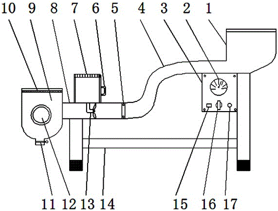
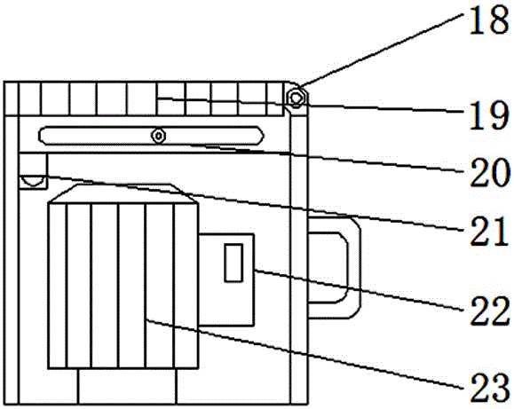
[0015] refer to Figure 1-2 , an automatic chip removal device for a CNC machine tool, comprising a control panel 3, an S-shaped pipe 4, a motor box 7, a straight pipe 8, a chip removal bin 9, a speed knob 16, a heat dissipation port 19 and a motor 23, and an S-shaped pipe 4 The chip removal interface 1 is installed on the right side, and a support frame 14 is installed under the chip removal interface 1. The S-shaped pipe 4 is connected with the straight pipe 8 through the connecting frame 5. A control panel 3 is installed below the S-shaped pipe 4. A speed knob 16 is installed on the surface of the panel 3, a tachometer 2 is installed above the speed knob 16, an in...


PUM


Abstract

The invention discloses an automatic chip discharging device for a numerical control machine tool. The automatic chip discharging device comprises a control panel, an S-shaped pipeline, a motor box, a straight pipe, a chip discharging bin, a rotating speed rotary knob, a heat dissipation opening and a motor. A chip discharging connector is arranged on the right side of the S-shaped pipeline, and a supporting frame is arranged below the chip discharging connector. The S-shaped pipeline is connected with the straight pipe through a connecting frame. The control panel is arranged below the S-shaped pipeline. The rotating speed rotary knob is arranged on the surface of the control panel. A revolution meter is arranged above the rotating speed rotary knob. An indicator lamp is arranged on the right side of the rotating speed rotary knob. A power switch is arranged on the left side of the rotating speed rotary knob. The motor box is arranged above the straight pipe. A draught fan is arranged in the straight pipe. According to the automatic chip discharging device, a controller is arranged and can be used for adjusting the rotating speed of the motor, when large waste chips are encountered, the rotating speed of the motor can be increased, the suction force of the draught fan is made to be increased, and it is guaranteed that the waste chips are thoroughly discharged.

Description

technical field [0001] The invention relates to the technical field of numerical control machine tools, in particular to an automatic chip removal device for numerical control machine tools. Background technique [0002] The main function of the automatic chip removal device for CNC machine tools is to collect various metal or non-metallic waste chips generated by the CNC machine tool during work, and transfer the waste chips to the collection bin for collection for unified processing. The usual chip removal device There are scraper type, chain plate type and spiral type, etc. The structure of the traditional chip removal method is relatively simple, and the effect of chip removal is not very ideal, and there will still be waste chips that are not collected, so that there will be waste chips in the environment of the staff, which is easy to Inhaled into the body by the user, thereby affecting the health of the user. Contents of the invention [0003] The purpose of the pr...

Claims


Application Information

Patent Timeline
Patent Type & Authority Applications(China)
IPC IPC(8): B23Q11/00
CPCB23Q11/0046
Inventor 张民胜
Owner 张民胜
Why Eureka
Try Eureka